What type of preamp are you designing? If it's typical preamp before poweramp, i don't see it so hard with a 3k load. 600ohm load will be trivial for most opamps. You will still need to drive the cable reactance. Ideally something similar to ultra low. noise headphone amplifier would be the best. Simply one opa1612 in parallel perchannel is more than enough.Depends on the input impedance of your audio interface. That will be parallel with however you load it. And when paralleling resistors, the smaller one dominates (ie: the 2 parallel can never be larger than the smallest value). It works fine w/ the 4 or 8 ohms of a power amp, as they just pull the device input impedance down. Unfortunately it doesn't work the other way!
Who said anything about op-amps? Just playing w/ the JBOZ and variations. The output impedance of the original standard circuit is 1.6k.
Who said anything about op-amps? Just playing w/ the JBOZ and variations. The output impedance of the original standard circuit is 1.6k.
So what is it for? Does it sit between your line level source and power amp? I have searched on it still not quite sure what it is. If it is, why bother with inferior design when you can make a much higher performance one with opamp?
Anyway if you want to test a circuit with 1.6k output impedance, you can add more series resistance between output and interface input. You are not measuring the absolute output but the distortion right? 1/3 or 1/4 of the level at interface input won't hurt too much.
Because it's fun. The thread is here:
Jfet BOZ
I see you're one of those "every preamp should be made with opamps and have the lowest THD you can achieve". And every power amp should be class AB with tons of global NFB. To each their own. It takes 5 seconds to breadboard one of these and test. I'll be moving on to buffered outputs, current sources, and cascodes. Just learning the ins and outs of solid state. And for the record, my current phono stage and preamp both utilize op-amps, so I have no problem with them. Just thought your reply was funny.
As for the series resistance, how does dropping the level help? Does it somehow match the impedance to the interface? I always though low-out, high-in was what you should strive for
The load impedance seen from the preamp is the added resistance + the input impedance of your Beringer. The reduced level is unwanted side effect, which isn't too bad. You can make the load to 10kohm or more if you do like this.Because it's fun. The thread is here:
Jfet BOZ
I see you're one of those "every preamp should be made with opamps and have the lowest THD you can achieve". And every power amp should be class AB with tons of global NFB. To each their own. It takes 5 seconds to breadboard one of these and test. I'll be moving on to buffered outputs, current sources, and cascodes. Just learning the ins and outs of solid state. And for the record, my current phono stage and preamp both utilize op-amps, so I have no problem with them. Just thought your reply was funny.
As for the series resistance, how does dropping the level help? Does it somehow match the impedance to the interface? I always though low-out, high-in was what you should strive for
Another way is to cascade another opamp based preamp/buffer with high input impedance that way the loading is put on the second preamp. You can then measure your preamp with no issue.
The load impedance seen from the preamp is the added resistance + the input impedance of your Beringer. The reduced level is unwanted side effect, which isn't too bad. You can make the load to 10kohm or more if you do like this.
Another way is to cascade another opamp based preamp/buffer with high input impedance that way the loading is put on the second preamp. You can then measure your preamp with no issue.
Thanks...I'll give it a try!
Gentlemen, please stay on topic.
Enoch, please show a loopback to see the capabilities of the cheap Behringer UM2, thank you.
I learned today that the input/USB/sound card device is the limiting factor using advanced FFT like this.
Enoch, please show a loopback to see the capabilities of the cheap Behringer UM2, thank you.
I learned today that the input/USB/sound card device is the limiting factor using advanced FFT like this.
Gentlemen, please stay on topic.
Enoch, please show a loopback to see the capabilities of the cheap Behringer UM2, thank you.
I learned today that the input/USB/sound card device is the limiting factor using advanced FFT like this.
What exactly is off topic? It's pertaining to distortion measurement using REW.
"I see you're one of those "every preamp should be made with opamps and have the lowest THD you can achieve". And every power amp should be class AB with tons of global NFB. To each their own. It takes 5 seconds to breadboard one of these and test. I'll be moving on to buffered outputs, current sources, and cascodes. Just learning the ins and outs of solid state. And for the record, my current phono stage and preamp both utilize op-amps, so I have no problem with them. Just thought your reply was funny."
etc.
etc.
Just addressing what he said. What is the point of being on a forum without some banter.
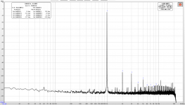
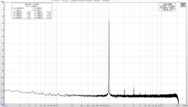
Anyhow, loopbacks of the UM2. It's a noisy environment, so that shows (or there is a lot of noise associated w/ the device). Both voltages were calibrated to 400mV RMS. First is using the internal generator, and the second is using the Akitika. No idea why the dBFS scale is showing up different on both of them. The voltage was measured and I calibrated that in REW. I assume that is why it's showing a higher relative noise on the Akitika graph (since the fundamental is lower). Clearly the Akitika is an improvement.
Also to note is that I cleared my calibration file before running these so they are legit. Using that feature really makes even this lowly UM2 a decent instrument to measure distortion as it cancels out the device pretty well.
Internal Generator:

Akitika:

Anyhow, loopbacks of the UM2. It's a noisy environment, so that shows (or there is a lot of noise associated w/ the device). Both voltages were calibrated to 400mV RMS. First is using the internal generator, and the second is using the Akitika. No idea why the dBFS scale is showing up different on both of them. The voltage was measured and I calibrated that in REW. I assume that is why it's showing a higher relative noise on the Akitika graph (since the fundamental is lower). Clearly the Akitika is an improvement.
Also to note is that I cleared my calibration file before running these so they are legit. Using that feature really makes even this lowly UM2 a decent instrument to measure distortion as it cancels out the device pretty well.
Internal Generator:
Akitika:
Last edited:
And I've asked before but no one replied. Why do my images show up as fuzzy and compressed? They are hosted remotely and look fine there.
Don’t know why but when I link an image hosted elsewhere, it shows up just the same resolution. You might try uploading images to DIYA server as attachment. That way, image link can never be broken for perpetuity.
Don’t know why but when I link an image hosted elsewhere, it shows up just the same resolution. You might try uploading images to DIYA server as attachment. That way, image link can never be broken for perpetuity.
Thanks for the reply! Weird that yours show up fine. As for the attachments, I didn't even see that option before! I thought all I could do is insert an image. Let's try that:
Attachments
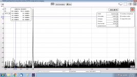
Here is a measurement using my Behringer 202HD and the LT AN67 signal generator as shown on these threads. EOSC10Kv3 - LT AN67 10kHz oscillator : new updated version !

Received my Focusrite yesterday looks pretty good this is a loopback using the Focusrite and REW generator.
Looks good. You might try changing the plot and sampling. The plot is a little “ragged” looking as it is.
I have been traveling, but have sorted the loopbacks out for a Focusrite Clarett. Ready to hook up some amplifiers and do the RTA analysis of them.
I connected my Behringer UM2 sound card to my laptop with REW running, then conneted it to the output of a B1 Korg triode preamp. As soon as I made the connections to the output, the KORG plate voltage went to 12v+. I had it adjusted to 9.5v, I disconnected the Behringer ASAP, no damage to the Korg.
Is there a sound card which will work on preamps like the B1 Korg?
Is there a sound card which will work on preamps like the B1 Korg?
I don't know. If that is something that would cause the plate voltage to rise on it's own, I'll try again. I'm taking a break from it the rest of this week and weekend, vintage racing at Road America, time to play with my Lotus before I go back to it. Thanks for the suggestion, I'll post results.
- Home
- Design & Build
- Software Tools
- How to - Distortion Measurements with REW