Right.The second stage transistors vbe is dependent on the first stage transistors vbe. So unless the vbe is tightly matched between the N and P devices, production build will be problematic.
This might work to solved the vbe issue.
Marantz use this solution, usually with one more cascode stage over Q1 and Q5.
I would use KSC1845/KSA992 instead of the TO-126 transistors.
Sajti
Interesting design T - I look forward to seeing it built up and to heart what the listening impressions are!
Nice one, spladski, optimized to the last detail. And your comp is just perfect.This might work to solved the vbe issue.
I don't think it is possible to get better with any emitter degeneration.
As you had seen, lot of aspect loose their harmony, driver with less current than VAS etc.
Time to explore other frontends, don't you think ?
Thanks, Bonsai. Lot of work to come to make-it feasible IRL.Interesting design T - I look forward to seeing it built up and to heart what the listening impressions are!
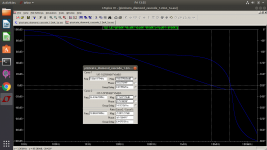
Some minor adjustments to lose a point on the distortion. 1KHz 0.000046%, 20KHz 0.00061%.
This front end, is a new front end compared to the original. Its properties haven't been explored. The vbe issue has been ameliorated. However, selection of input transistors will entail a re-balance of the circuit which needs to be described for potential builders. The temperature stability also needs examination. Others are free to dive in and launch new approaches. Presentation of the positive and negative aspects of a given design should be provided so that forum members can make a valued judgement and learn from the exercise.
This front end, is a new front end compared to the original. Its properties haven't been explored. The vbe issue has been ameliorated. However, selection of input transistors will entail a re-balance of the circuit which needs to be described for potential builders. The temperature stability also needs examination. Others are free to dive in and launch new approaches. Presentation of the positive and negative aspects of a given design should be provided so that forum members can make a valued judgement and learn from the exercise.
Attachments
Spladski, you are the man !This front end, is a new front end compared to the original.
Exactly what we can expect from collaboration between members of the forum: Understanding others ideas, bringing his ones, out of the usual tracks.
Attachments
Last edited:
Found the problem with the fast edges square waves VS current in the input transistor. C1 & C9 have to be removed.
Now, I think we can increase the current in the input transistors and improve their HF behavior.
AS I'm a real newbee in simulations, some expert could explore the input transistors mismatches and the variation of temperatures behaviors ?
The brilliant Spladski "Emerald" (Its not a 'diamond' anymore, isn't-it ?) need to be explored deeply.
I don't think we have to worry anymore about VBE mitmatches, as, now, most of the currents are set by the current sources.
After this, it will be time to refine the VAS and driver currents balance, and we will be on ... something ?
At least, this is a demonstration that, working together in a positive and collaborative way instead of the ones against the others can bring, at least, the joy that surrounds my day, sharing the Spladski's one I can feel ;-)
Last edited:
the variation of temperatures behaviors ?
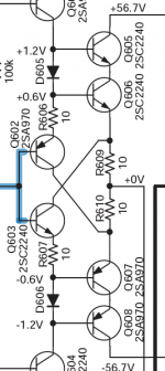
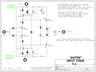
Use the Marantz HDAM style input stage, which reduce the dissipation of the 2nd stage. There will be no problem with the different temperature.
Sajti
Attachments
Mark, assuming that the two current sources will differ slightly, how is that balanced? Are you assuming a servo, not shown?
Jan
Jan
It's not perfectly balanced nor does it attempt to be; that's why it uses "only" 1% resistors and more importantly, that's why C1 is present and a servo is absent.
But the people who built it and installed it (it's on an interchangeable 4-pin daughter card), like the sound of the music it plays. More than they like the sound of the other four circuit designs on the other four daughter cards. Look at "M2x" post #1 for all five schematics.
But the people who built it and installed it (it's on an interchangeable 4-pin daughter card), like the sound of the music it plays. More than they like the sound of the other four circuit designs on the other four daughter cards. Look at "M2x" post #1 for all five schematics.
Mark, assuming that the two current sources will differ slightly, how is that balanced? Are you assuming a servo, not shown?
Jan
Generally the offset is few mV only, with selected bjt pairs. I use almost same topolgy in the volume buffer. Nice sounding!
Sajti
We are at the stage of exploration/proof of concept. When all the flaws will be well known, with the everybody's help, it will be time to address them the best way.
For the moment -but is-it necessary to tell ?- the purpose is
200W CFA, low distortion, DC coupled, input stage with max gain in balanced diamond style, cascode VAS+driver, Power Fets, minimal active devices.
The reason of those choices: each of those principles had been experienced as sounding well together.
Well, Dadod had demonstrated in an amazing way what it is possible to achieve with many refinements, let's see if it's possible to fight with an abacus in front of a computer ;-)
Now that the critical flaw (input VBE mismatch) had been (OMHO) addressed, ar minimal cost (no added parts, no added distortion) time to enter in the details ?
Thanks to all the valuable participants to use the available sim files and propose practical analysis results and /or their solutions.
By example, If the input stage devices mismatches is really a problem, we will have several possible solutions. One of them to use some That300 with Mark's suggestion. But it will be marching on the Dadod's track ;-)
The original file contain a DC servo. It has been removed from the ASC files just to accelerate the sims.
I have the idea, when the amp will be advanced, to add a protection based on:
An ultimate amp protection circuit ?
As this protection is extracting the difference between input and output signals, I will explore some added error correction, at this time and for the fun, from the same circuit. What do-you think ?
I'm on this at this moment.
- Home
- Amplifiers
- Solid State
- Pizzicato, a 200W low distortion CFA amplifier