How does the S/N behave if Ic is constant - this is the most practical scenario. I assume it will also peak at say 1mA but then drop off more rapidly as Rcart decreases and increases about the 1 mA level ( or whatever is selected).
Yes - I meant to say Rcart is the independent variable. I think fixing Ic like this is probably the more usual case unless you are expecting to deal only with ultra low Rcart. But, it also seems with this topology Ic is best up in the 10 mA range.
I posted the wrong chart and then deleted the whole post.
If Rs is variable and Ic is constant then 1/2gm the collector current noise contribution is constant, the input impedance is constant, so the input divider divides both the signal and the noise by the same ratio given by the variable Rs. Therefore, for large Rs, the SNR decreases, since the signal is constant and the Rs noise increases as SQRT(Rs). No optimum in this case.
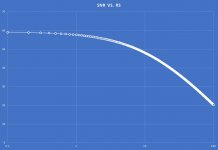
To me it was a surprise that the SNR is optimum at such low collector currents. But then I have no idea what is the best metric for a MC cartridge + head amp, the total noise, or the SNR. That's because when the stylus hits the vinyl, the SNR of the MC cartridge + head amp is much better than the vinyl anyway, even if it's not optimized. OTOH, for the idle TT, it is the total noise that matters, to avoid the idle hiss. So it could very well be that this Ic optimum is a result of academic relevance only.
And yes, I was always wondering if the "optimum load" in the MC cartridge pamphlet has any relevance and what would be the side effects of going much lower than the recommendation. Hence my question about reading the MC cartridge almost in short (lower input impedance compared to Rs).
Attachments
Last edited:
Attached is a plot of SNR[dB] vs. Ic[mA] for Rs=12ohm Vs=0.4mV and Rbb=0. Note the Ic horizontal log scale. The optimum Ic goes down when Rbb is considered.
Thank you Ovidiu, this is interesting result
I was always wondering if the "optimum load" in the MC cartridge pamphlet has any relevance and what would be the side effects of going much lower than the recommendation.
I have no answer, but my customers prefer several hundred Ohm load
The manufacturers factsheet tells that there is global feedback, so read Stereophiles report with suspicion.
Hans
I dont know where you got the manufactureres factsheet from but on the BMC homepage, the key features of the circuit are desribed as
1. symmetrical current input
2. BJT common base topology
3. feedback free circuit
4. fully balanced circuit
5. symmetrical single ended class A output stage
6. fully passive RIAA eq between stages
The input circuit is furthermore described as a DC balanced symmetrical design where the cartridge current is injected leading to a current shift which is converted into an output voltage. So it looks like a circuit very similar to the ones discussed in this thread but symmetrical and balanced.
The unweighted noise measurements are somehow reasonable (manufacturers values match the sterophile measurements) but the difference of 30 dB+ when A-weighting can only mean that there is a huge 1/f noise component at low frequencies.
Syn08
From your last plot, I would assume the S/N declines as Ic goes up because the current density increases and therefore the shot noise? It seems almost counter intuitive to me looking at his plot that you would not want to minimize Ic. Ok, that also has to be balanced with fbb’ and re’ I guess but what’s your and Scott’s take on that?
From your last plot, I would assume the S/N declines as Ic goes up because the current density increases and therefore the shot noise? It seems almost counter intuitive to me looking at his plot that you would not want to minimize Ic. Ok, that also has to be balanced with fbb’ and re’ I guess but what’s your and Scott’s take on that?
Syn08
From your last plot, I would assume the S/N declines as Ic goes up because the current density increases and therefore the shot noise? It seems almost counter intuitive to me looking at his plot that you would not want to minimize Ic. Ok, that also has to be balanced with fbb’ and re’ I guess but what’s your and Scott’s take on that?
The explanation is in the same post. No, the reason is that the Rs noise (the X axis variable) increases, everything else, including Ic shot noise, is constant. It is perfectly intuitive.
"If Rs is variable and Ic is constant then 1/2gm the collector current noise contribution is constant, the input impedance is constant, so the input divider divides both the signal and the noise by the same ratio given by the variable Rs. Therefore, for large Rs, the SNR decreases, since the signal is constant and the Rs noise increases as SQRT(Rs). No optimum in this case."
I understand this - clear from the formula.
My question is a bit different. If the Ic increases (so current desintiy goes up) surely the shot noise must go up as well or am I not understanding the mechanism correctly? Obviously I can understand that at some point rbb' or re' contributions must be a factor - but my main question is about the shot noise.
Thanks for making me aware of these facts, I obviously had an old factsheet.I dont know where you got the manufactureres factsheet from but on the BMC homepage, the key features of the circuit are desribed as
1. symmetrical current input
2. BJT common base topology
3. feedback free circuit
4. fully balanced circuit
5. symmetrical single ended class A output stage
6. fully passive RIAA eq between stages
The input circuit is furthermore described as a DC balanced symmetrical design where the cartridge current is injected leading to a current shift which is converted into an output voltage. So it looks like a circuit very similar to the ones discussed in this thread but symmetrical and balanced.
The unweighted noise measurements are somehow reasonable (manufacturers values match the sterophile measurements) but the difference of 30 dB+ when A-weighting can only mean that there is a huge 1/f noise component at low frequencies.
Looking at their website now with the most recent info, I see:
Amplifier Circuit
1. Balanced Current Injection input.
2. Common base circuit for highest bandwidth.
3. "Automatic" gain adjustment.
4. Feedback-free circuit with very short signal path.
So you are right, a common base circuit sounds like the Leach / Lee topology.
I'm intrigued by their "automatic" gain adjust.
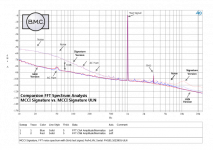
There is also a picture of the amps noise production, see below, just following the Riaa curve as expected, nothing special.
No sign of "huge 1/f components".
The large spread between both channels in SNR of resp 83.2dB and 71.8dB SNR is already quite strange, but 100dB-A after A-weighting is out of the question.
Hans
Attachments
Thank you for sharing all this info.I posted the wrong chart and then deleted the whole post.
If Rs is variable and Ic is constant then 1/2gm the collector current noise contribution is constant, the input impedance is constant, so the input divider divides both the signal and the noise by the same ratio given by the variable Rs. Therefore, for large Rs, the SNR decreases, since the signal is constant and the Rs noise increases as SQRT(Rs). No optimum in this case.
To me it was a surprise that the SNR is optimum at such low collector currents. But then I have no idea what is the best metric for a MC cartridge + head amp, the total noise, or the SNR. That's because when the stylus hits the vinyl, the SNR of the MC cartridge + head amp is much better than the vinyl anyway, even if it's not optimized. OTOH, for the idle TT, it is the total noise that matters, to avoid the idle hiss. So it could very well be that this Ic optimum is a result of academic relevance only.
And yes, I was always wondering if the "optimum load" in the MC cartridge pamphlet has any relevance and what would be the side effects of going much lower than the recommendation. Hence my question about reading the MC cartridge almost in short (lower input impedance compared to Rs).
Since you refer to 1/2gm, I suppose you went back to the complementary Lee version and that you are still working with a 0.4mV Cart signal.
What is not mentioned is what collector current you used, 1mA or 0.2mA ?
With a 1mA collector current and Rs=0.1 Ohm, LTSpice gives a SNR of 75dB and with 0.2mA a SNR of 72dB.
However, your image is showing ca. 58dB for Rs =0.1 Ohm.
Am I missing something ?
Hans
BMC "Automatic gain adjust" simply means that gain is inversely proportional
to pickup coil resistance in a circuit like this.
Ahh - that makes perfect sense - assuming output rises with coil resistance (probably true in most cases since more turns = more output and higher coil resistance.
If the Ic increases (so current desintiy goes up) surely the shot noise must go up as well or am I not understanding the mechanism correctly?
You probably don’t; as the collector current increases, the collector current shot noise increases. However, the RTI voltage noise contribution of the collector current shot noise decreases. 1/2gm is the RTI equivalent resistance noise contribution of the collector shot noise current.
For Hans, no, the 1/2gm equivalent input noise resistance is not for the complementary version. Calculate the collector shot noise current multiplied by the input impedance and convert to an equivalent resistance, you’ll get the 1/2gm.
Interestingly, I have a similar plot to the BMC one above using a JFET input - design similar to the Faraday but with just a single 22 Ohm resistor in the source circuit and a switched 235 or 470 Ohm feedback from the gm helper transistor. My measurements are dBV and the output is 350mV at max gain 500uV in. The noise floor is about 3-5 dB lower and the THD 2nd and 3rd H -110 dB. I suspect the source feeding into the BMC is the same 10 Ohm trick JA mentioned in the Stereophile review - my Inverse RIAA Zout is 40 Ohms.
Seems in practice there may not be much difference between circuits, although paper specs seem to indicate otherwise..
Seems in practice there may not be much difference between circuits, although paper specs seem to indicate otherwise..
Thank you for sharing all this info.
Since you refer to 1/2gm, I suppose you went back to the complementary Lee version and that you are still working with a 0.4mV Cart signal.
What is not mentioned is what collector current you used, 1mA or 0.2mA ?
With a 1mA collector current and Rs=0.1 Ohm, LTSpice gives a SNR of 75dB and with 0.2mA a SNR of 72dB.
However, your image is showing ca. 58dB for Rs =0.1 Ohm.
Am I missing something ?
Hans, are you sure you simulated at Vs=0.4mV? I get from calculation SNR 74dB at Vs=1mV, Rs=0.1ohm, Ic=1mA, so this covers the delta to your simulation almost exactly if you used Vs=1mV. SNR always depends on the input signal level, that's yet another reason why it is not my favorite noise metric.
Maybe you can explain in more detail.BMC "Automatic gain adjust" simply means that gain is inversely proportional
to pickup coil resistance in a circuit like this.
Automatic gain adjust is not the same as inversely proportional to coil resistance.
From 1R to 30R this differs 20dB in gain for a 3R input.
And what happend when switching for a Cart with a lower or a higher output voltage ?
So I'm still intrigued and have no idea what this could mean.
Hans
Yes, you can assume that mc cart output rises with higher turns count.
If that were the case, it would be nice and explain BMC's intention.
But I dare to doubt that output voltage and Rcart are one of a pair..
There are a loads of 0.5mV Carts differing in Rcart a factor 10 or 20.
Hans
It is even 3dB better, because I simulated with a differential version, sorry for that.Hans, are you sure you simulated at Vs=0.4mV? I get from calculation SNR 74dB at Vs=1mV, Rs=0.1ohm, Ic=1mA, so this covers the delta to your simulation almost exactly if you used Vs=1mV. SNR always depends on the input signal level, that's yet another reason why it is not my favorite noise metric.
Now having switched back to a SE version I have again adjusted Ic=1mA by lowering the battery voltage to 1.21 Volt.
Noise as you can see is 51.12nV with 0.1 Ohm source, so SNR is 20*log(0.4mV/51,12nV) = 78dB.
For a 1mV input signal SNR would even have been 86dB.
And yes, the Rb's for the two ZTX devices are properly adjusted to resp. 1.5 and 1.2 Ohm.
Hans
Attachments

It is even 3dB better, because I simulated with a differential version, sorry for that.
Now having switched back to a SE version I have again adjusted Ic=1mA by lowering the battery voltage to 1.21 Volt.
Noise as you can see is 51.12nV with 0.1 Ohm source, so SNR is 20*log(0.4mV/51,12nV) = 78dB.
For a 1mV input signal SNR would even have been 86dB.
And yes, the Rb's for the two ZTX devices are properly adjusted to resp. 1.5 and 1.2 Ohm.
Hans, that's for the symmetrical complementary version, calculations are for only half of that.
But in general, I have no idea what you are doing there and where is the discrepancy (if any) is coming from. Since simulation is so much easier, I am sure you could easily figure it out. SNR is by definition the ratio of signal and noise powers at the output, BTW.
Maybe you can explain in more detail.
Automatic gain adjust is not the same as inversely proportional to coil resistance.
From 1R to 30R this differs 20dB in gain for a 3R input.
And what happend when switching for a Cart with a lower or a higher output voltage ?
So I'm still intrigued and have no idea what this could mean.
Hans
The german text on their webpage describes this 'automatic gain adjust' as already mentioned due to the gain dependency from genrator resistance. They had more High output MCs in mind as those have significantly higher Rgen. So the amp is compatible with Low and High output MC carts.
For all reason you mentioned with respect to high variability even between different LOMC cartridges there are different gain settings via jumpers on the board possible (low, medium and high - +12dB, +6dB and +0dB).
So bottom line 'automatic gain adjustment' is marketing blabla
- Home
- Source & Line
- Analogue Source
- Richard Lee's Ultra low Noise MC Head Amp