hello prasi that speaker protector should use ya ax14 does not have pro terminal
Hello My PCB design of AX-14 does not have pro terminal and associated components on boards. Its based on correct schematic as given my Mr. Mile in post 22.
A$-14 build
Bit confused with mention of having a separate wire from input ground to star ground, does that not effectively bypass C13 or is the connection on the ground side of C13?
Also with prasi's AX-14 board does the use of the anti parallel diodes perform the earth connection above. And how is R23 used?
Thanks
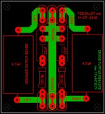
Ok.Here is an explanation. I have provided 3 options for grounding in case anyone experiences hum/ ground loop.
Option 1: Populate the anti parallel diodes D6/D7 and R23 and don't connect the input ground to anywhere else. This a classic case of lifting the ground as given in https://www.updatemydynaco.com/documents/GroundingProblemsRev1p4.pdf
Option 2: dont populate D6/D7/R23. Run a separate input ground wire from input GND to PSU star ground.
Option 3: Replace R23 with a link. This is a last ditch effort to eliminate the hum.
Its a trial and error method. I can not make a perfect PCB without knowing what PSU and what other circuits and what source (and how sources are grounded , etc) people will be connecting to this amplifier. SO better to have options.
Hope it makes things clear.
regards
Prasi
Bit confused with mention of having a separate wire from input ground to star ground, does that not effectively bypass C13 or is the connection on the ground side of C13?
Also with prasi's AX-14 board does the use of the anti parallel diodes perform the earth connection above. And how is R23 used?
Thanks
C13 goes from SGND to power GND. I'm not sure how much difference it makes but it probably does no harm.
C13 goes from SGND to power GND. I'm not sure how much difference it makes but it probably does no harm.
Mr. Mile said, its only for test.
SGND to be connected to PGND.
100W Ultimate Fidelity Amplifier
regards
Prasi
Well, i gave up my previous AX14 board, even though I managed to reduce the offset voltage it was producing a very loud howling noise. Made a fresh board , offset is 48mV. Now there is no howling but there is a MOTOR BOAT sound also turn on noise, clueless and somewhat morally down. Any help is greatly appreciated and thanks in advance.
Regards.
Anoop
Regards.
Anoop
Well, i gave up my previous AX14 board, even though I managed to reduce the offset voltage it was producing a very loud howling noise. Made a fresh board , offset is 48mV. Now there is no howling but there is a MOTOR BOAT sound also turn on noise, clueless and somewhat morally down. Any help is greatly appreciated and thanks in advance.
Regards.
Anoop
please post clear photos of top and bottom of your build
AX14 Pictures
Regards.
Anoop 🙂
Thanks for considering my issue. Im attaching the pictures.please post clear photos of top and bottom of your build
Regards.
Anoop 🙂
Attachments
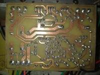
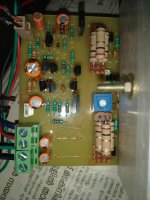
Thanks for considering my issue. Im attaching the pictures.
Regards.
Anoop 🙂
please post the schematic and pcb files you used ......
please post the schematic and pcb files you used ......
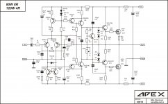
Attaching,
For c9 and 10, i used 22pf as Mr miles suggested elsewhere in the thread.
Regards.
Anoop
Attachments
Your above circuit is missing the parallel resistor for the inductor for it to be called as a Thiele network.
Regarding your problems with AX-14, please check your schematic thoroughly against Mr. Mile's schematic and clean up your sch for wrong parts / wrong orientation , etc.
Ensure you use genuine parts.
Check your etched PCB for any shorts, discontinuity, etc.
measure twice, solder once including the transistors.
Check and recheck your soldering for bad/cold joints and solder bridges, etc.
Power up with a MBT on the mains line and measure offset/ bias .
If everything is ok, connect a small test speaker and listen for any hum / buzz, hot zobel resistors, etc, at a very low volume.
Voila, you passed first stage of amplifier building.
Thiele NW
Regards.
Anoop.
Actually the inductor would be wound around it and fit on to the pcb together.Your above circuit is missing the parallel resistor for the inductor for it to be called as a Thiele network.
Regarding your problems with AX-14, please check your schematic thoroughly against Mr. Mile's schematic and clean up your sch for wrong parts / wrong orientation , etc.
Ensure you use genuine parts.
Check your etched PCB for any shorts, discontinuity, etc.
measure twice, solder once including the transistors.
Check and recheck your soldering for bad/cold joints and solder bridges, etc.
Power up with a MBT on the mains line and measure offset/ bias .
If everything is ok, connect a small test speaker and listen for any hum / buzz, hot zobel resistors, etc, at a very low volume.
Voila, you passed first stage of amplifier building.
Regards.
Anoop.
Aha! such a clever design.
Dont you think you should have included that info when you posted your design?
Similarly you should have posted the info about wrong tranny footprint in your sch with your AX-14 schematic, which sajti had to find out.
I wasted , may be half an hour , trying to debug... then found out that you had it all wrong with cap orientations.
So many people had to waste their time for what was a perfect build (which was checked many times over by yourself).
One more thing, you posted a design having many many problems, then when stevin asked for a close up pictures, you posted an APEX design of the build.
Which one did you build exactly?
I am curious, so would be everyone else...
Regards
Prasi
AX 14
Sorry to all who spent their valuable time for me. It took some days for me to yell for help, all these times I was on to that board. It is, I admit I committed some mistakes while creating the schematic in easyeda, like the cap orientation pointed out by Mr Prasi, and the transistor one pointed out by Mr sajti, which was, in due course of time I forgot while posting for help for it has been some time.
I request Mr Prasi to read Post#11488, some questions might be answered.
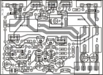
The reason I abandoned the board is, it was made with a cheap copper clad board which was all messed up because of the troubleshoot work, then I began to think the howling might be due to a faulty PCB design (my design of course), so I directly took the APEX design and made it, which was what I posted for Stevin, and when ask me for the schem and pcb design I used, what would be better ? The stuff I used or some link to another file ?
As far as thiele NW is concerned, it is also a general practice to wind the inductor around the resistor, and it was a PCB not a schematic. All I wanted to know if there would be any issues due to closeness of two inductors.
I will no more trouble any one. I will try myself, being a tried and tested amp I might be successful or look elsewhere.
Thanks for all who spent their precious time for me.It was my first fully self made amp.
Regards.
Aha! such a clever design.
Dont you think you should have included that info when you posted your design?
Similarly you should have posted the info about wrong tranny footprint in your sch with your AX-14 schematic, which sajti had to find out.
I wasted , may be half an hour , trying to debug... then found out that you had it all wrong with cap orientations.
So many people had to waste their time for what was a perfect build (which was checked many times over by yourself).
One more thing, you posted a design having many many problems, then when stevin asked for a close up pictures, you posted an APEX design of the build.
Which one did you build exactly?
I am curious, so would be everyone else...
Regards
Prasi
Sorry to all who spent their valuable time for me. It took some days for me to yell for help, all these times I was on to that board. It is, I admit I committed some mistakes while creating the schematic in easyeda, like the cap orientation pointed out by Mr Prasi, and the transistor one pointed out by Mr sajti, which was, in due course of time I forgot while posting for help for it has been some time.
I request Mr Prasi to read Post#11488, some questions might be answered.
The reason I abandoned the board is, it was made with a cheap copper clad board which was all messed up because of the troubleshoot work, then I began to think the howling might be due to a faulty PCB design (my design of course), so I directly took the APEX design and made it, which was what I posted for Stevin, and when ask me for the schem and pcb design I used, what would be better ? The stuff I used or some link to another file ?
As far as thiele NW is concerned, it is also a general practice to wind the inductor around the resistor, and it was a PCB not a schematic. All I wanted to know if there would be any issues due to closeness of two inductors.
I will no more trouble any one. I will try myself, being a tried and tested amp I might be successful or look elsewhere.
Thanks for all who spent their precious time for me.It was my first fully self made amp.
Regards.
The layout you just built is sound. If it is not working then you have done something wrong. Either a bad part, wrong orientation, bad solder joint, solder bridge, something. It is not a problem with the layout. I and many others have built this amp with many substitute parts and all have been successful. You need to double check each part and make sure they are installed correctly. This amp will play.
Go to post #3404 100W Ultimate Fidelity Amplifier and you will see that I built it many ways and the only problems I had were self inflicted. Once everything was corrected they played beautifully.
Blessings, Terry
Go to post #3404 100W Ultimate Fidelity Amplifier and you will see that I built it many ways and the only problems I had were self inflicted. Once everything was corrected they played beautifully.
Blessings, Terry
AX14 motor boat sound
Actually i was a little heartbroken today and not in a mood to do much trouble shooting, however I won't leave him without making a good boy. Once i reach home i will take him up.
Regards.
Thanks for the concern,The layout you just built is sound. If it is not working then you have done something wrong. Either a bad part, wrong orientation, bad solder joint, solder bridge, something. It is not a problem with the layout. I and many others have built this amp with many substitute parts and all have been successful. You need to double check each part and make sure they are installed correctly. This amp will play.
Go to post #3404 100W Ultimate Fidelity Amplifier and you will see that I built it many ways and the only problems I had were self inflicted. Once everything was corrected they played beautifully.
Blessings, Terry
Actually i was a little heartbroken today and not in a mood to do much trouble shooting, however I won't leave him without making a good boy. Once i reach home i will take him up.
Regards.
- Home
- Amplifiers
- Solid State
- 100W Ultimate Fidelity Amplifier