But I guess from GM, that neither port location on or off axis, or driver location over the port, is all that important compared to distance from throat, size, shape, depth, etc.
Off axis means not in line with a reference axis, no more, no less.
Correct WRT a Synergy concept since it's presumed to have a high compression chamber [low pass filter] which will have no meaningful 1/2 WL eigenmodes that NC535 is referring to due to having a large blockage to reduce internal volume and create a 'squish' area around the vent [see hemi-head combustion chamber design theory].
A Unity concept OTOH will have a theoretically infinite number of 1/2 WL eigenmodes that sums to a huge dip in the response since it's just a cavity formed by the cone/horn body junction, which as NC535 has already pointed out sets the usable HF BW.
GM
Tom Danley didn't express them this way. That would have been ambiguous.I agree with you 😉 It's just the way most people express this.
Yes I know all this, I'm just talking about the placement of the woofer vs their taps. Not the taps to eachother. All my taps will be placed following the 1/4th WL principle (and taking the CD length in consideration).
See another example of the SH96 where you can clearly see the woofer only has its edge placed over the tap, not its center.
OK, let's try it this way......... let's assume the driver is rectangular and that sealed to a horn body creates a so called 'open cylinder' though closed at both ends: Resonances of open air columns
As I understand the theory:
If the vent axis is centered on the pipe's axis, i.e. in the middle, then you get the widest BW.
If the vent is at the extreme end from the pipe's axis [dead center], then its HF BW is ~halved due to the pipe's harmonic notch.
If the vent
GM
True you can't simulate the effect of the tap location relative to the center of the woofer cone in HR. Experience shows you won't have a problem unless the furthest distance from the tap to any point on the woofer cone approaches half a wavelength. If you are in the "approaches" region as opposed to "exceeds" it likely still works, just causes you some gain near XO, which should be no big deal as you are targetting an acoustic output curve for the woofer that is -6 db down at XO.
'fartest" point will turn out to be almost the diameter of the woofer no? Or how would you decide what makes out this 'farthest' distance? From the center of the port, or the literal farthest point away from a part of the cone? - Also, do I take the square root of the Sd as cone area, or do I take the given "15 inch" as the diameter of a given woofer?
re'
"Then I need to decide how to place the woofers over the port. Just 1 woofer with 2 corner placed elongated (aka rectangular) slots which would mean a symmetrical placement OR 1 slot located to the very side of the woofer, which means being able to use twice as much woofers which gains me 6dB. The woofers are too big to place 2 on the same side of the horn (so 4 woofers in total) AND place those slots symmetrical over the woofer."
two woofers on opposite sides of the horn with two slots per woofer is easiest to build and they can be larger woofers and still play just as high because the slots are closer to woofer center
I agree it's the easiest, and I'll start off like this, but want to know if I can convert the horn into a 4 driver synergy later on.
trying to squeeze 4 woofers on can be challenging, woofers on each side of the horn tend to bump into each other. do you need that +6 db? If your system includes subs, as it should, then I doubt you do, but I can understand you wanting it anyway.
Looking into trying to match the HF output, preferably with a +6dB.. this is ofcourse very challenging.
Not only will you have 6db more output but you will also need 6 db more port area, which means increased diffraction off the slots and more disturbance of the polar pattern by the slots
Why would you need 6dB more port area? Acoustic coupling would only happen once they leave the ports, so doubling of the woofer (non-coupled) is 3dB, or more logicaly speaking: twice the woofers is twice the port area. I do agree that I want to keep the port area as small as reasonable to decrease chances of diffraction etc. If I want to use high SPL I'll need pretty big ports too, so maybe even bigger than a 1:10 ratio.. maybe the 1:7 Danley uses?
right - only double, was being too cute repeating 6 db
but it will depend on how you use the additional woofer displacement - for additional SPL or extended low end or some mix of the two. You have the choice in a sealed box with equalization.
This is where the HR simulation comes in. Choose port size to keep particle velocity in the throat port below 17m/s. Particle velocity apparently rises as frequency decreases at constant SPL so extending the low end has a port size cost as well. and the interactions are complex. If you change the ratio of port area to port length, you change the frequency response.
If you really want/need high SPL, consider going vented. You'll get it without increasing throat port area; potentially even reducing it because the lowest half octave or so will go through the vent instead of the port.
I would derive the diameter from the Sd. But the worst case distance depends on where the port is relative to the center of the woofer cone, at least for the 2 woofer case.
Converting the horn to 4 woofers later on? Not likely unless you plan for that up front, just based on box size and construction issues.
Matching HF output not usually so hard on a constant directivity horn because the HF roll off due to the horn reduces the CD's effective sensitivity
... this would induce some...cancelation issues within the own driver?
As it will be a 2-way, I will only have LFrange/lowmidrange woofers. Crossover at 650hz 0dB/700hz -3db. So a 1/2 WL of 24,5cm.
Hi Maarten
This is quite a smart question.
As Bill Waslo has correctly pointed out, the important distance is 1/4 WL not 1/2.
So for 650 Hz it's only ~ 125 mm.
If you have a port near the suspension then you have a potential problem as the speaker cone diameter increases past that size.
Whereas you would be OK with a speaker cone up to 250 mm if the port was in the middle.
But that probably conflicts with the need to have the port near the throat.
I would put the woofer as close as possible to the throat and place the port to put the 1/4 WL notch at the frequency you want.
Ideally that would be in the centre of the woofer, whether this is feasible depends on the woofer size, what did you have in mind?
Best wishes
David
Last edited:
True, destructive combination starts when the distance exceeds 1/4 wavelength but because that distance in this case is only to a small fraction of the cone area, it doesn't become significant until the distance is quite a bit larger. That is a judgement based on experience - back in the day I got 8" midwoofer with an edge located port on a synergy to respond usably well past 1 khz.
But don't take my word for it - do a 10 minute experiment. Mount your woofer against a large scrap of plywood with a hole in it and do a close mic frequency response at the hole. Do this with woofer centered on the hole and offset.
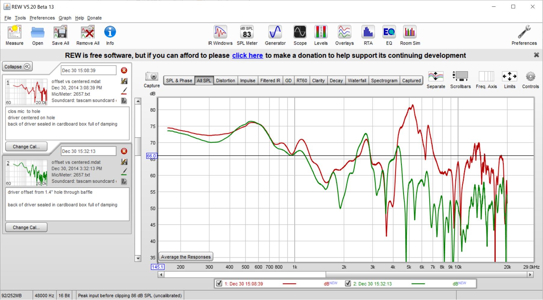
the above data taken almost 5 years ago is for an 8FE200 which has an Sd of 191 cm2 for an effective diameter of (only) 6.13"
The offset driver peaks at 1078 Hz while the centered driver peaks at 1104 hz. Interesting that the curve for the offset driver is smoother, symmetry is not our friend!
But don't take my word for it - do a 10 minute experiment. Mount your woofer against a large scrap of plywood with a hole in it and do a close mic frequency response at the hole. Do this with woofer centered on the hole and offset.
the above data taken almost 5 years ago is for an 8FE200 which has an Sd of 191 cm2 for an effective diameter of (only) 6.13"
The offset driver peaks at 1078 Hz while the centered driver peaks at 1104 hz. Interesting that the curve for the offset driver is smoother, symmetry is not our friend!
Attachments

...the above data...is for an 8FE200 which has an Sd of 191 cm2 for an effective diameter of (only) 6.13"...
Thanks for the real data, almost too real because there seems to be some cone break up, cancellation and cavity resonances, hard to sort it all out.
The peak at ~ 1100 Hz looks like a resonance of the speaker itself since its almost independent of the port details.
The port itself is not a point source and the maths is complicated because we are not in the far field where the maths becomes simpler.
If the offset port centre is about 3" from the centre of the speaker then we expect 1/2 cancellation at ~ 2.2 kHz and it should start to roll off at 1/4 WL = 3", say 1.1 kHz.
This looks about correct, with the earlier mentioned speaker resonance also near 1.1 kHz superimposed.
I calculate the first null is actually a little less than 1/2 WL so the fact it is just a little less than 2 kHz rather than 2.2 kHz makes sense.
Or it could be luck with the estimates!
So I think the 1/4 WL rule of thumb looks pretty close.
...the curve for the offset driver is smoother, symmetry is not our friend!
Yes, fair point, "ideal" position to minimise cancellation is not the best for smoothness.
I don't plan to make an axisymmetric horn - for similar reason.
The push to reduce the port to throat distance means the port(s) are likely to be offset a little towards the throat anyway but an useful point to keep in mind.
Best wishes
David
Thanks for going through the arithmetic. I was just happy to find the measurements. A 5 cycle FDW cleans up the picture. I added a clos mic of the unbaffled driver there for comparison.
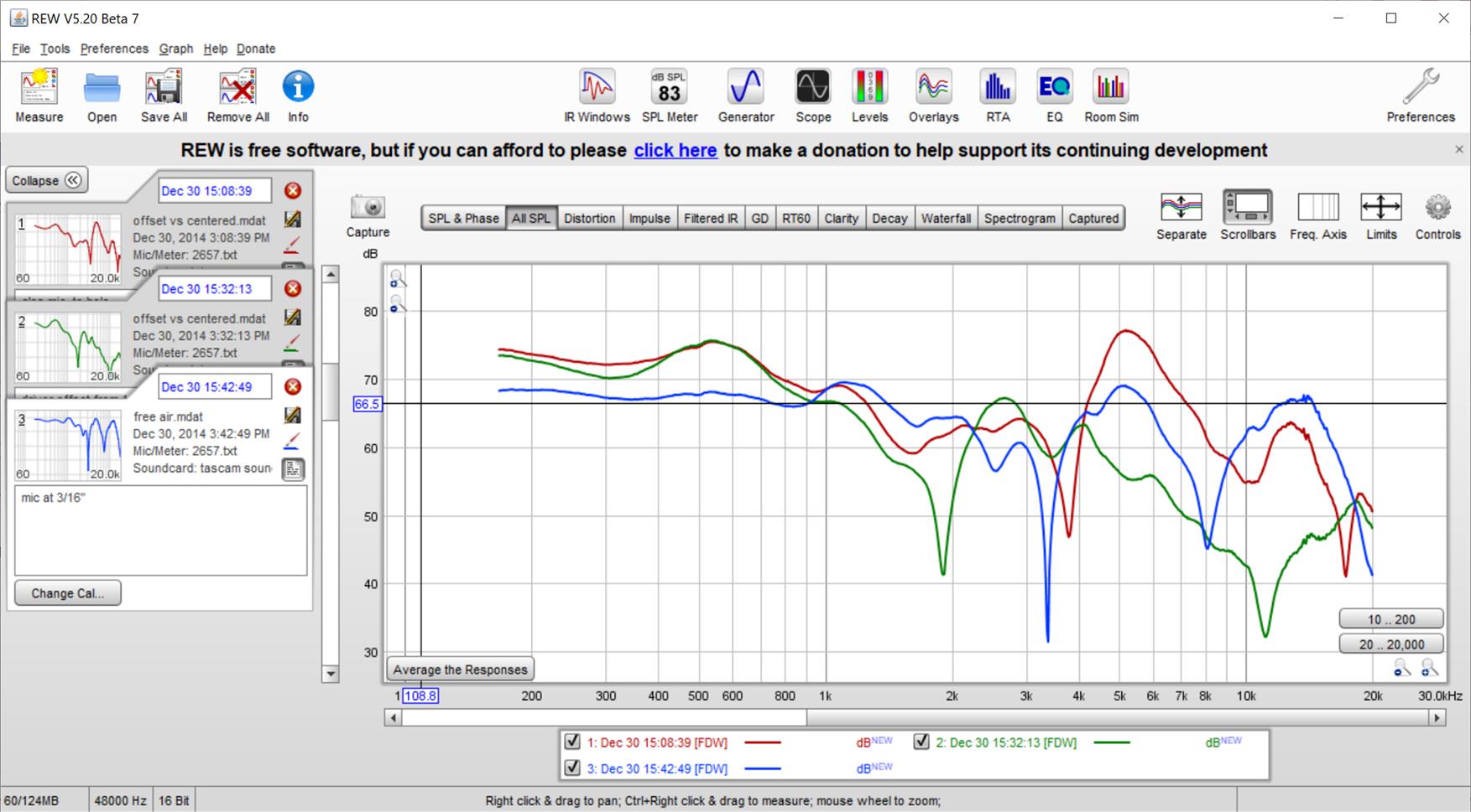
So 1/4 wave rule successfully predict where it starts to roll off but that is not the highest possible XO, depending on several other constraints that would exist and that was my initial point. The rolloff due to this effect is gradual and can be equalized up to a point in order to make a design "work". In this picture you can easily see how much eq would be required to make up for this rolloff. Tuning of the bandpass chamber might also be effective in this regard. In fact, bandpass chamber acoustic low pass filtering might have some responsibility for the roll off that we see.
So 1/4 wave rule successfully predict where it starts to roll off but that is not the highest possible XO, depending on several other constraints that would exist and that was my initial point. The rolloff due to this effect is gradual and can be equalized up to a point in order to make a design "work". In this picture you can easily see how much eq would be required to make up for this rolloff. Tuning of the bandpass chamber might also be effective in this regard. In fact, bandpass chamber acoustic low pass filtering might have some responsibility for the roll off that we see.
Attachments

Last edited:
right - only double, was being too cute repeating 6 db
but it will depend on how you use the additional woofer displacement - for additional SPL or extended low end or some mix of the two. You have the choice in a sealed box with equalization.
This is where the HR simulation comes in. Choose port size to keep particle velocity in the throat port below 17m/s. Particle velocity apparently rises as frequency decreases at constant SPL so extending the low end has a port size cost as well. and the interactions are complex. If you change the ratio of port area to port length, you change the frequency response.
Smart! I didnt consider modelling it like a vented cab.
If you really want/need high SPL, consider going vented. You'll get it without increasing throat port area; potentially even reducing it because the lowest half octave or so will go through the vent instead of the port.
I dont like the quality decrease I'll get from it. Also, wouldnt even know how to start modelling it I guess. Or is it just the vented port "placed" at it's tuning frequency?
I would derive the diameter from the Sd. But the worst case distance depends on where the port is relative to the center of the woofer cone, at least for the 2 woofer case.
Converting the horn to 4 woofers later on? Not likely unless you plan for that up front, just based on box size and construction issues.
Yes I'm planning for it right now. For now I'll start with 2 woofers with 2 taps each (symmetrical), and make it so I can later add 2 woofers (using 1 each). I would have to enlarge the ports later, or just start with the ports large enough. I just bumped into the problem of not being able to fit ports for 4x18" woofers with a 10:1 ratio in the horn. I could do it, but it's gonna be hard.. Then I would need one 4cm (1,5") wide and 30cm (~12") long tap for each woofer.
Matching HF output not usually so hard on a constant directivity horn because the HF roll off due to the horn reduces the CD's effective sensitivity
Didnt take that in account.. thats true. My horn is not a true CD though. It's more a horn like the Klipsch K402. In any case, how much dB would you lose in a CD? Estimated? Then I can maybe match the woofers better.
How much eq for the CD? your guess is as good as mine, easily 10 db though. Look at the K402 MEH thread for an indication
Hi Maarten
This is quite a smart question.
As Bill Waslo has correctly pointed out, the important distance is 1/4 WL not 1/2.
So for 650 Hz it's only ~ 125 mm.
If you have a port near the suspension then you have a potential problem as the speaker cone diameter increases past that size.
Whereas you would be OK with a speaker cone up to 250 mm if the port was in the middle.
But that probably conflicts with the need to have the port near the throat.
I would put the woofer as close as possible to the throat and place the port to put the 1/4 WL notch at the frequency you want.
Ideally that would be in the centre of the woofer, whether this is feasible depends on the woofer size, what did you have in mind?
Best wishes
David
I'm looking into using 18 inch'ers, but thats looking less and less feasible I agree. So you recommend using a 1/4th WL ánd using the farthest point on the cone surface to the farthest point of the tap? Than I wouldnt be able to use any woofer bigger than 10", and would only be able to place the tap in the center OR use x2 symmetric taps to minimise the distance?
How much eq for the CD? your guess is as good as mine, easily 10 db though. Look at the K402 MEH thread for an indication
I never read anything about the dB loss in that thread.. 10dB is a lot though ö I would not need to boost anything to reach that frequency range hopefully. -10dB also means a lot less wooferpower than I orginally calculated.
Ok be just to clearify everything up:
- 1: do I use 1/4th or 1/2th WL?
- 2: do I use the woofer center or the farthest point on the cone surface?
- 3: do I use the tap center, closest point or farthest point vs the woofer?
- 1: do I use 1/4th or 1/2th WL?
- 2: do I use the woofer center or the farthest point on the cone surface?
- 3: do I use the tap center, closest point or farthest point vs the woofer?
...A 5 cycle FDW cleans up the picture. I added a clos mic of the unbaffled driver there for comparison.
Yes, that helps quite a bit, demonstrates the ~1.1 kHz speaker resonance I expected, and the fall off from ~1 kHz to a 2 kHz null with the offset port.
Really nice fit to the theory.
So 1/4 wave rule successfully predict where it starts to roll off...and can be equalized up to a point.
OK, your point wasn't clear to me.
I wouldn't be keen to use much past 1/4 WL, it disturbs me to have part of the cone that actually works in opposition to what we want!
But it's not an unbreakable limit, makes sense to use the roll off as part of crossover shape to filter some distortion too, as we discussed in another thread.
Best wishes
David
...the farthest point on the cone surface to the farthest point of the tap?...
- 1: do I use 1/4th or 1/2th WL?
- 2: do I use the woofer center or the farthest point on the cone surface?
- 3: do I use the tap center, closest point or farthest point vs the woofer?
This stuff does not have a perfectly sharp cut off beyond which there will be failure.
So I don't have definitive answers, just rules of thumb about what looks likely to work and what is probably a waste of time.
I use the centre of the tap to the furthest point of the cone.
< 1/4 WL is OK
More than that is steadily more problematic, up to 1/2 WL which is unacceptable.
To do it properly we need to do a detailed simulation with numerical solver software like Comsol or ABEC.
Comsol looks very nice but is expensive and I've never used it.
The free version of ABEC is nice but I haven't done a simulation in this sort of detail.
And I don't have experimental test yet, I have just started to think seriously about a rebuild of my 1.5" compression driver + 15" woofer into a multi-entry horn system.
Like you, I think a ~650 crossover looks reasonable.
The 10" "limit" is for the actual cone size so a 10" nominal speaker should be OK.
I am not sure yet if I can use my current 15"s, it's borderline.
I assume Danley and JBL would not waste money on a mid if it was easy to transition directly to a 15" woofer.
Of course their SPL requirements are a little different to home use.
Chris's system has a K402 horn with 15" woofers.
I have 18" subs so a 10" or 12" woofer would match without problems.
Best wishes
David
Last edited:
Hi Dave:
"steadily more problematic" sums it up nicely.
My offset vs centered measurements were on a piece of plywood over an absorber filled cardboard box - so much easier than learning ABEC or even waiting for it to run!
You should be able to reach down to subs with 8" woofers, 10's for sure, depending of course on how loud you listen.
When I looked at 15" woofers with 1.5" CD, I was put off by the size of the ports and how close they had to be to the apex of the horn. Do a 3-way with a 1" CD and those large woofer ports can be twice as far down the horn.
..."steadily more problematic" sums it up nicely.
Thank you, I do worry myself to try to find the correct words.
When I looked at 15" woofers with 1.5" CD, I was put off by the size of the ports and how close they had to be to the apex of the horn...
So, what do you think of Chris's 2 way with 15" woofers?
I have more problem with the size of the horn rather than the ports, I am constrained to 24" in width.
A horn on the diagonal is limited to less than about 32", dependent on mouth round over.
Best wishes
David
For reference, the horn I'm using is even bigger. It has a 108x75cm horn, and is 38cm deep (42 with the CD to mouth adapter).
Bigger horn surface means less influence on refraction I figure.
Bigger horn surface means less influence on refraction I figure.
Chris benefits from having a great horn and a very large one. The port size is larger than I would like but it certainly seems to work in that context likely because so many other things are right and the port size might only affect corners of the pattern. But the last I heard from him, he was thinking about ways to reduce the port size, working off the observation that a short port need not have as much area as a long one.
A smaller horn doesn't have as much room for large woofers but also loses control of directivity earlier. One can extend the directivity with additional, overlapping drivers outside the horn that cover both sides of the point where the horn loses control of directivity. If you go this direction, you'll find that you don't need or want 15" drivers within the horn. Thinking ahead to this architecture, I built some 15" slot loaded subs using AE TD15H. To extend the HF range, I made the slot a very high aspect ratio conical horn and found they responded smoothly to 650 Hz.
A smaller horn doesn't have as much room for large woofers but also loses control of directivity earlier. One can extend the directivity with additional, overlapping drivers outside the horn that cover both sides of the point where the horn loses control of directivity. If you go this direction, you'll find that you don't need or want 15" drivers within the horn. Thinking ahead to this architecture, I built some 15" slot loaded subs using AE TD15H. To extend the HF range, I made the slot a very high aspect ratio conical horn and found they responded smoothly to 650 Hz.
- Status
- Not open for further replies.
- Home
- Loudspeakers
- Multi-Way
- Synergy horn: port location