Would the effect of off-axis port placement in a synergy be detrimental to the sound quality? Or would it be manageable? I know Danley does rounded rectangular slots completely to the side of the woofers, so I guess it works.
Or what would be a good rule of thumb to determine how far off the woofer center you can have its port.
Thanks in advance
Maarten
Or what would be a good rule of thumb to determine how far off the woofer center you can have its port.
Thanks in advance
Maarten
Hi Maarten,
What do you mean by 'off-axis' port placement?
As in, off-axis to what? Or perhaps, what is 'on-axis' port placement?
Not trying to be pedantic, I've just never been able to get an answer from folks who use this term as to what is meant....
Away from that question, my understanding is that ports in the horn corners cause the least horn interference with the HF/VHF output.
Not sure how that has anything to do with woofers centers though...??
Best, mark
'Axis' = centerline, so on axis would be the driver, port centered on the horn axis and with DSL proving that this isn't an issue even when the vent is [partially] over the surround, much ado about nothing since we're dealing with a high compression ratio [CR] in the driver's pistonic [acoustically stiffest] BW.
Re corner venting, Tom and I had this 'conversation' way back with in the early days of the Unity as I was viewing vent location from a race car aerodynamics POV and he seemed primarily interested in HF output, but in retrospect, the boundary layer in sharp corners can act as a scavenging [vacuum] pressure or at least getting some corner loading, increasing vent efficiency = smaller, shorter vents.
No clue whether there's enough to impact a MEH's vent's performance or not, but figured that all things considered, he'd chosen the best overall location.
GM
Last edited:
Hi Maarten,
What do you mean by 'off-axis' port placement?
As in, off-axis to what? Or perhaps, what is 'on-axis' port placement?
Not trying to be pedantic, I've just never been able to get an answer from folks who use this term as to what is meant....
Away from that question, my understanding is that ports in the horn corners cause the least horn interference with the HF/VHF output.
Not sure how that has anything to do with woofers centers though...??
Best, mark
I mean the center of the woofer/LF driver relative to the port it's gonna be firing through. Not the location of the port relative to the horn. You're right about that. Corner placement in the horn, but then how I place the woofers over this port is my issue. Centered over it, or could I also put the woofers in a way that only the margin of the woofer is placed over the port.
I figure this would induce some time allignment and cancelation issues within the own driver?
Thanks guys,
So I take it from GM that off-axis means port(s) are off the horns horiz and vert center lines, but that Droco uses off-axis to mean the driver's center does not sit directly over the port no matter where the post is.... pls correct if either take is misunderstood.
But I guess from GM, that neither port location on or off axis, or driver location over the port, is all that important compared to distance from throat, size, shape, depth, etc.
I mean the center of the woofer/LF driver relative to the port it's gonna be firing through. Not the location of the port relative to the horn. You're right about that. Corner placement in the horn, but then how I place the woofers over this port is my issue. Centered over it, or could I also put the woofers in a way that only the margin of the woofer is placed over the port.
I figure this would induce some time allignment and cancelation issues within the own driver?
Its been observed that if you have the port on one edge of a driver's cone than you can get some roll off due to cancellation from sound coming from the far edge. You do not want the diameter of the cone to approach half a wavelength at the XO. This is a potential issue more for mids than woofers..
Placing the port at the center of the cone minimizes this distance but is at odds with the more important requirement to get the port within a quarter wavelength of the CD's reflecting surface.
Thanks guys,
So I take it from GM that off-axis means port(s) are off the horns horiz and vert center lines, but that Droco uses off-axis to mean the driver's center does not sit directly over the port no matter where the post is.... pls correct if either take is misunderstood.
But I guess from GM, that neither port location on or off axis, or driver location over the port, is all that important compared to distance from throat, size, shape, depth, etc.
Off-axis just implies all the non apex-mounted (so perpendicular axis) drivers, aka the woofers. Simple as that. Just semantics maybe?
Its been observed that if you have the port on one edge of a driver's cone than you can get some roll off due to cancellation from sound coming from the far edge. You do not want the diameter of the cone to approach half a wavelength at the XO. This is a potential issue more for mids than woofers..
Thanks Jack, that point was new to me.
@ Maarten
Yep, all on board now, if ports aren't on horn center lines, mids' or woofers', they be off-axis 🙂
Although I'd much prefer to hear that 'ports are placed centrally in the horn, or placed in corners', etc.
Would the effect of off-axis port placement in a synergy be detrimental to the sound quality? Or would it be manageable? I know Danley does rounded rectangular slots completely to the side of the woofers, so I guess it works.
Or what would be a good rule of thumb to determine how far off the woofer center you can have its port.
Thanks in advance
Maarten
Is this for the woofer or the midrange taps?
With the midrange taps, the location of the port is fairly critical, because we're talking about wavelengths that are ten inches long. A difference of 2.5" is a difference of a quarter wavelength.
With the woofer taps, you can basically go crazy, because the wavelengths are so long. 350Hz is a meter long. It's downright difficult to screw up the woofer taps.
Its been observed that if you have the port on one edge of a driver's cone than you can get some roll off due to cancellation from sound coming from the far edge. You do not want the diameter of the cone to approach half a wavelength at the XO. This is a potential issue more for mids than woofers..
Placing the port at the center of the cone minimizes this distance but is at odds with the more important requirement to get the port within a quarter wavelength of the CD's reflecting surface.
Is this for the woofer or the midrange taps?
With the midrange taps, the location of the port is fairly critical, because we're talking about wavelengths that are ten inches long. A difference of 2.5" is a difference of a quarter wavelength.
With the woofer taps, you can basically go crazy, because the wavelengths are so long. 350Hz is a meter long. It's downright difficult to screw up the woofer taps.
As it will be a 2-way, I will only have LFrange/lowmidrange woofers. Crossover at 650hz 0dB/700hz -3db. So a 1/2 WL of 24,5cm.
- So how do I apply this 24,5cm? Is this the max distance I can have between the center of the woofer and the tap? So I would be good with a 18" woofer with its tap in the farrest corner possible, as this would still only be 23cm (which is not really possible because I wouldnt be able to make it big enough and put it in the corner).
- If so, is it the center of the tap, or the nearest edge?
Thanks Jack, that point was new to me.
@ Maarten
Yep, all on board now, if ports aren't on horn center lines, mids' or woofers', they be off-axis 🙂
Although I'd much prefer to hear that 'ports are placed centrally in the horn, or placed in corners', etc.
I agree with you 😉 It's just the way most people express this.
As it will be a 2-way, I will only have LFrange/lowmidrange woofers. Crossover at 650hz 0dB/700hz -3db. So a 1/2 WL of 24,5cm.
- So how do I apply this 24,5cm? Is this the max distance I can have between the center of the woofer and the tap? So I would be good with a 18" woofer with its tap in the farrest corner possible, as this would still only be 23cm (which is not really possible because I wouldnt be able to make it big enough and put it in the corner).
- If so, is it the center of the tap, or the nearest edge?
My attitude is "when in doubt, copy Tom Danley":
Two Way Synergy???
All the pics and information you could ever want for a two-way Unity horn is here.
My attitude is "when in doubt, copy Tom Danley":
Two Way Synergy???
All the pics and information you could ever want for a two-way Unity horn is here.
I like the linked thread, beautifull speaker!, but I really have specific theoretical questions, I dont want to copy a design.
The question now is primarly how far I can place the woofer ports away from the center.
My attitude is "when in doubt, copy Tom Danley":
Two Way Synergy???
All the pics and information you could ever want for a two-way Unity horn is here.
Also, yes! Copy Danley 🙂 It's because the woofers are placed so far away from the taps that I figured it be at least possible. Just want to know what to take in account when doing this. Need to know the things I'm giving up to see if its worth it (placing them to the side of the taps allows more woofers).
Attachments
I like the linked thread, beautifull speaker!, but I really have specific theoretical questions, I dont want to copy a design.
The question now is primarly how far I can place the woofer ports away from the center.
I applaud you for not wanting to copy a design but that means you have to do the design yourself. Assuming you have drivers and a horn picked out, the next step would be to put together a hornresp model. That is the best way to answer the question about where to put the ports.
Let me see if I can help you with the semantics...
Suppose you decide to put the ports 4" from the throat. What does that mean precisely? Draw or imagine a line along the axis of the horn. Measure 4" down that axis from the CD exit at the throat. Now project orthogonally from that 4" point on the axis out to the horn walls. In a CAD system, you could draw a disc centered on that point and orthogonal to the axis line. Anywhere the disc intersected with the horn walls counts as 4" from the throat for this purpose. Somewhere on that line of intersection you would place the center of a round port or the centroid of some other shaped port.
You are anticipating 650 Hz XO, a wavelength of 20.8" so you can place the ports as much as 5.2" from the phase plug of the CD, which for most CDs is where the reflection we are concerned about comes from. So, coincidentally, 4" from the throat might not be a bad starting point for your model.
This quarter wave constraint isn't the only consideration on port locations but sets a maximum and is the most important one, consult the patents for guidance.
As it will be a 2-way, I will only have LFrange/lowmidrange woofers. Crossover at 650hz 0dB/700hz -3db. So a 1/2 WL of 24,5cm. ...
The critical distance (too far, no way to recover) is 1/4 wavelength not 1/2, so 123mm. Which keep in mind that would put the reflection notch just inside the band edge, so you really want it closer than that. And it also includes the distance inside the HF driver to it's diaphragm, so closer still. That is the distance from the taps to the tweeter along the axis of the horn. You also will want to keep the woofer ports within 1/4 wave from each other, assuming that you want the waveguide to set the directivity (so all the taps act like one driver). You can put them further to extend a horn's directivity a little if the crossover range is near where the horn loses it, but that gets kind of tricky in both distance and crossover.

I applaud you for not wanting to copy a design but that means you have to do the design yourself. Assuming you have drivers and a horn picked out, the next step would be to put together a hornresp model. That is the best way to answer the question about where to put the ports.
Let me see if I can help you with the semantics...
Suppose you decide to put the ports 4" from the throat. What does that mean precisely? Draw or imagine a line along the axis of the horn. Measure 4" down that axis from the CD exit at the throat. Now project orthogonally from that 4" point on the axis out to the horn walls. In a CAD system, you could draw a disc centered on that point and orthogonal to the axis line. Anywhere the disc intersected with the horn walls counts as 4" from the throat for this purpose. Somewhere on that line of intersection you would place the center of a round port or the centroid of some other shaped port.
You are anticipating 650 Hz XO, a wavelength of 20.8" so you can place the ports as much as 5.2" from the phase plug of the CD, which for most CDs is where the reflection we are concerned about comes from. So, coincidentally, 4" from the throat might not be a bad starting point for your model.
This quarter wave constraint isn't the only consideration on port locations but sets a maximum and is the most important one, consult the patents for guidance.
I actually already did all the modelling on the synergy, it's just that the woofer location vs the tap placement is something I cant model. Tap placement is fixed on the horn (also I think it's the edge of the tap to the reflective surface), and will be at 13cm (~5"), as this gets me the aucoustic crossover I need.
Then I need to decide how to place the woofers over the port. Just 1 woofer with 2 corner placed elongated (aka rectangular) slots which would mean a symmetrical placement OR 1 slot located to the very side of the woofer, which means being able to use twice as much woofers which gains me 6dB. The woofers are too big to place 2 on the same side of the horn (so 4 woofers in total) AND place those slots symmetrical over the woofer.
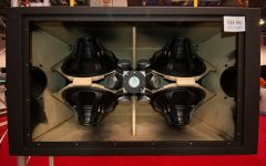
That is what all this is about. As you can see in the picture from the SH96, you can see the 15" woofers only overlap on the very edge with the horn, where their elongated rectangular slot is.
Last edited:
The critical distance (too far, no way to recover) is 1/4 wavelength not 1/2, so 123mm. Which keep in mind that would put the reflection notch just inside the band edge, so you really want it closer than that. And it also includes the distance inside the HF driver to it's diaphragm, so closer still. That is the distance from the taps to the tweeter along the axis of the horn. You also will want to keep the woofer ports within 1/4 wave from each other, assuming that you want the waveguide to set the directivity (so all the taps act like one driver). You can put them further to extend a horn's directivity a little if the crossover range is near where the horn loses it, but that gets kind of tricky in both distance and crossover.
Yes I know all this, I'm just talking about the placement of the woofer vs their taps. Not the taps to eachother. All my taps will be placed following the 1/4th WL principle (and taking the CD length in consideration).
See another example of the SH96 where you can clearly see the woofer only has its edge placed over the tap, not its center.
Attachments
Yes I know all this, I'm just talking about the placement of the woofer vs their taps. Not the taps to eachother. All my taps will be placed following the 1/4th WL principle (and taking the CD length in consideration).
See another example of the SH96 where you can clearly see the woofer only has its edge placed over the tap, not its center.
True you can't simulate the effect of the tap location relative to the center of the woofer cone in HR. Experience shows you won't have a problem unless the furthest distance from the tap to any point on the woofer cone approaches half a wavelength. If you are in the "approaches" region as opposed to "exceeds" it likely still works, just causes you some gain near XO, which should be no big deal as you are targetting an acoustic output curve for the woofer that is -6 db down at XO.
re'
"Then I need to decide how to place the woofers over the port. Just 1 woofer with 2 corner placed elongated (aka rectangular) slots which would mean a symmetrical placement OR 1 slot located to the very side of the woofer, which means being able to use twice as much woofers which gains me 6dB. The woofers are too big to place 2 on the same side of the horn (so 4 woofers in total) AND place those slots symmetrical over the woofer."
two woofers on opposite sides of the horn with two slots per woofer is easiest to build and they can be larger woofers and still play just as high because the slots are closer to woofer center
trying to squeeze 4 woofers on can be challenging, woofers on each side of the horn tend to bump into each other. do you need that +6 db? If your system includes subs, as it should, then I doubt you do, but I can understand you wanting it anyway
Not only will you have 6db more output but you will also need 6 db more port area, which means increased diffraction off the slots and more disturbance of the polar pattern by the slots
- Status
- Not open for further replies.
- Home
- Loudspeakers
- Multi-Way
- Synergy horn: port location