We are in agreement - I learned from those guys too! And compensation is pivotal and mathematically based and more people need to understand it fully, including me........
Hugh
Hugh
Hello Damir,
what transformer do you recommend for a class A 40W mono block? 2x24V AC with xxxVA?
BR
Günni
Hi Gunni,
This amp will take about 3A per rail with no signal, and you need double at full power.
I would say good choice will be 2x25V 6A, and to be on save side 10A, so 300VA to 500VA transformer for mono or 600VA to 800VA for stereo.
BR Damir
We are in agreement - I learned from those guys too! And compensation is pivotal and mathematically based and more people need to understand it fully, including me........
Hugh
We are lucky now with free spice software, no need to calculate, but still understanding is essential.

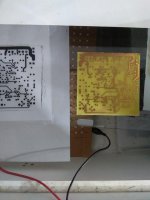
A very early progress
Attachments

Last edited:
Is it ok i continue posting here or does i need to start a new thread?
It is OK. I am interested about your build.
It is OK. I am interested about your build.
Ok thanks damir!
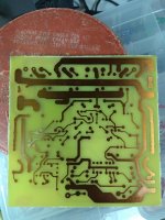
Drilled, not perfectly but acceptable.. 😉
Last picture, once again in the UV exposure for completely photoresist removal.
Attachments
Last edited:
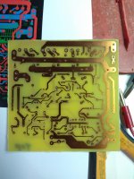
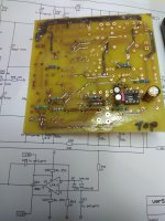
Starting to assembling.
Unfortunately i must start to desolder.
They are wrong polarity placed electrolytis at the offset controller power supply c22, c23.
Unfortunately i must start to desolder.
They are wrong polarity placed electrolytis at the offset controller power supply c22, c23.
Attachments
Last edited:
Starting to assembling.
Unfortunately i must start to desolder.
They are wrong polarity placed electrolytis at the offset controller power supply c22, c23.
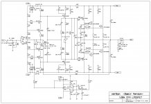
Wrong polarity on the schematic/pcb or?
Regards
Wrong on schematic,pcb is ok but was looking on schematic.Wrong polarity on the schematic/pcb or?
Regards

Wrong on schematic,pcb is ok but was looking on schematic.
Thanks Thimios, I missed that.
Attachments
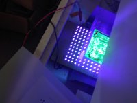
That's cool Thimos, using UV led's in your exposure frame.
Use BP (UES) ecaps and do not worry about polarity.
Use BP (UES) ecaps and do not worry about polarity.
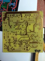
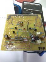
Small progress but i have many missing parts...
I have 0,22R & 0.33R non inductance.
I have 0,27R wire resistors.
I think that 0. 22R is ok.
I haven't boutique caps for compensation,so i will use multilayer for test.
I have 0,22R & 0.33R non inductance.
I have 0,27R wire resistors.
I think that 0. 22R is ok.
I haven't boutique caps for compensation,so i will use multilayer for test.
Attachments
Last edited:
Small progress but i have many missing parts...
I have 0,22R & 0.33R non inductance.
I have 0,27R wire resistors.
I think that 0. 22R is ok.
Yes you ca use 0.22R, I use 0.27 as I have those.
Yes you ca use 0.22R, I use 0.27 as I have those.
Thanks damir! 🙂
Another question, i see that Vbe multiplier isn't thermaly contact with the heatshink.
Is this really?
Is it because of latfets usage?
Last edited:
Thanks damir! 🙂
Another question, i see that Vbe multiplier isn't thermaly contact with the heatshink.
Is this really?
Is it because of latfets usage?
Yes, for lateral mosfet no need to be thermally connected to the heatsink.
The beauty of the lateral mosfet is the bias stability. I did up Bob Cordell's DH-220C design, it is rock steady, no bjt design can do this.
no bjt design can do this.
The Vbe transistors in my BJT CFP amps have also no contact with drivers/output/heatsink. Rock stable too 🙂
- Home
- Amplifiers
- Solid State
- Lateral CFA 120W - BSA