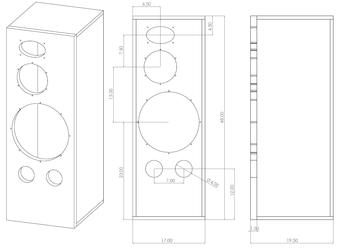
this is my proposal,
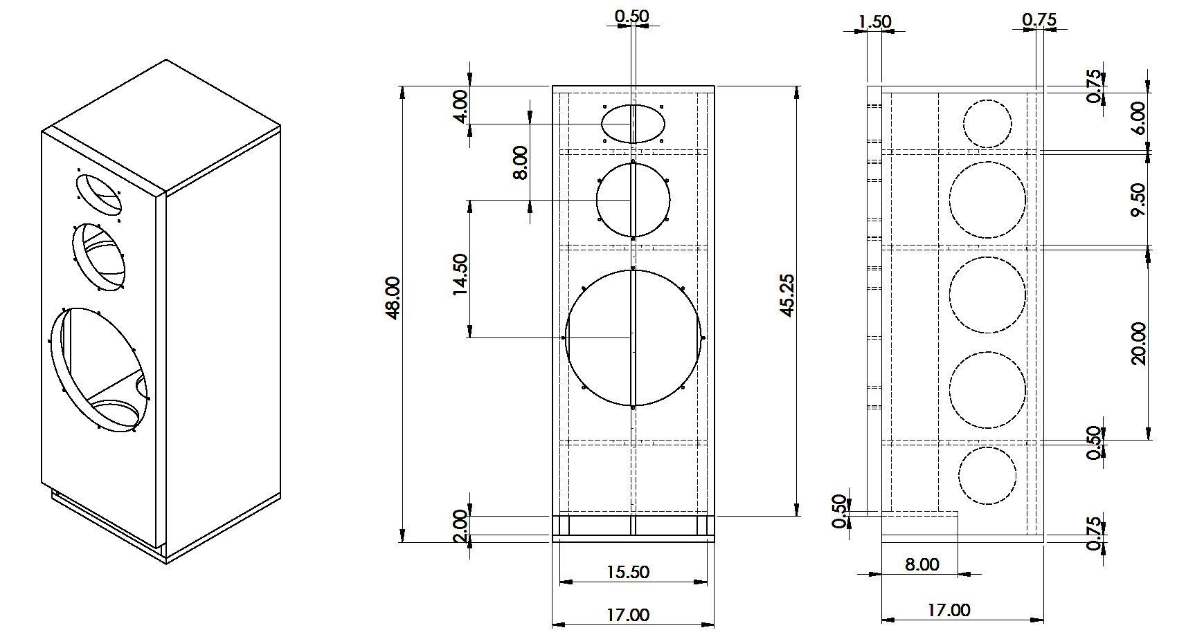
Volume is about 160L net. we can offset the mid and tweeter if needed.
You'll need a separate comparment for the midrange. Otherwise the woofer and midrange will interfere with each other via the their shared internal box volume.
I would suggest to offset the mid and tweeter away from the centerline to smear out baffle diffraction. A baffle diffraction simulator can be useful to determine the offset. I usually end up at left/right ratio close to the golden ratio. For the tweeter, the distance to top edge also may also be considered.
We had some heated discussion about the best position of the bass reflex port for the Monkey Coffin. In my tests, my favorite port placement was at the rear, near the center of the bass volume. With the port at the bottom (or top), higher modes of the woofer box seem to couple into the bass reflex port more than if the the port is at the center. However, others had different opinions on port placement, which may be worth to consider.
Production designs and simulations show improved dynamics with reduced resonances when the midrange box volume is large around the front baffle (dynamics) with thin on-wall absorption material, and has a rear tapered volume lightly filled with absorption material(resonances).
=========
The current cabinet design is optimized for simple straight cuts from a table saw, router, or CNC. A CNC Flat-pack is possible.
Edge Diffraction
1) Current 17" width design builders could add a second front baffle to allow modest edge bevels.
2) An 18" wide front baffle could be be 2-boards deep for minor edge treatment, or 3-boards deep "around the edges" for large radius or large bevel edge treatment. Does the extra volume from an 18" wide baffle improve ported bass performance?
Attachments
agreed, that's what i was about to bring up next. my focus here was the cabinet shape and size for bass volume and baffle difraction.You'll need a separate comparment for the midrange. Otherwise the woofer and midrange will interfere with each other via the their shared internal box volume.
thanks for the tip, I will offset the drivers in the next drawing and also will push the drivers down a bit.I would suggest to offset the mid and tweeter away from the centerline to smear out baffle diffraction. A baffle diffraction simulator can be useful to determine the offset. I usually end up at left/right ratio close to the golden ratio. For the tweeter, the distance to top edge also may also be considered.
interesting, i have no experience with that shape of bass port, i usually try this link to determine the port size for this box. we can go with two front firing ports in the middle of the front baffle (on top of LF driver), rear firing maybe a little difficult since having the speakers a foot away from the wall can be problematic for me, lets figure this out before I start cutting 😀, any simulations would be very welcome.We had some heated discussion about the best position of the bass reflex port for the Monkey Coffin. In my tests, my favorite port placement was at the rear, near the center of the bass volume. With the port at the bottom (or top), higher modes of the woofer box seem to couple into the bass reflex port more than if the the port is at the center. However, others had different opinions on port placement, which may be worth to consider.
one of the X designs uses a pyramid shape enclosure for the mid/high (fullrange) driver filled with pillow stuffing or some fiber insulation or something similar.. i think that would be a good idea here.Production designs and simulations show improved dynamics with reduced resonances when the midrange box volume is large around the front baffle (dynamics) with thin on-wall absorption material, and has a rear tapered volume lightly filled with absorption material(resonances).
The current cabinet design is optimized for simple straight cuts from a table saw, router, or CNC. A CNC Flat-pack is possible.
correct, this was one of the main goals here, to keep things simple for someone (like me) with basic carpentry skills.
Edge Diffraction
1) Current 17" width design builders could add a second front baffle to allow modest edge bevels.
2) An 18" wide front baffle could be be 2-boards deep for minor edge treatment, or 3-boards deep "around the edges" for large radius or large bevel edge treatment. Does the extra volume from an 18" wide baffle improve ported bass performance?
we can discus an 18 inch baffle,
as far as the rounded edges and triple front baffle thickness goes, I guess someone with more carpentry skills can do any changes they want
Last edited:
agreed, that's what i was about to bring up next. my focus here was the cabinet shape and size for bass volume and baffle difraction.
Ok -- but remember that the internal box for the midrange will be part of your volume calculation!
Production designs and simulations show improved dynamics with reduced resonances when the midrange box volume is large around the front baffle (dynamics) with thin on-wall absorption material, and has a rear tapered volume lightly filled with absorption material(resonances).
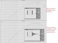
It's a bit hard to read the axis labels on the simulation curves, but I believe the resonance issue in your simulation is at 7 kHz. I would be surprised if the midrange would go so high in the Tower XL design. I don't remember what the x-over points are, but as long as the midrange is cut-off below 7 kHz, the resonance will not be an issue in this design.
Ok -- but remember that the internal box for the midrange will be part of your volume calculation!
if i remember correctly, needed volume for the mid was about <2L. don't quote me on that tho 😀
It's a bit hard to read the axis labels on the simulation curves, but I believe the resonance issue in your simulation is at 7 kHz. I would be surprised if the midrange would go so high in the Tower XL design. I don't remember what the x-over points are, but as long as the midrange is cut-off below 7 kHz, the resonance will not be an issue in this design.
The first XO by Paul was LR4 at 300 and 2000 Hz (post #732)
It's a bit hard to read the axis labels on the simulation curves, but I believe the resonance issue in your simulation is at 7 kHz.
The simulation for the Beyma 12Pd80ND in a rectangular volume + fiberglass on the walls produces a 5db resonance at 800Hz. A wide range of internal bracing can reduce cabinet resonances, engineers at B&W obtained the best sound using a large open rear volume for dynamics, followed by a tapered tube with absorption material to reduce resonances. Pyramid shapes performed almost as well as tube shapes..... constant rear volume reduction + increased absorption material. Angling one rear horizontal board behind the driver to create a triangle for absorption material is a good simplification which still leaves rear top-bottom free air flow for the woofer.
Hi,
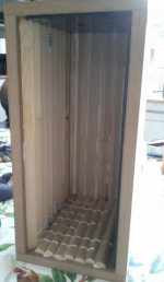
i've made three different mid cabinets but don't have measurements yet for all of them (similar speaker as towerXL, faital 8pr155 mid though). Will post here whenever i got silent time at home to take measurements.
Currently my big protobox has "triangular" enclosure for mid in it: straight top and sides, bottom in ~45 angle from frontpanel to top, maybe 5liters folume. The quick measurements showed dips so made two test enclosures. One with both sides angled , straight top and bottom. Third one is all straight sides but it is cabinet wide and as shallow as possible, only little room behind the driver for voicecoil vent. This is around 8cm depth if I remember, first resonance should be little under 2kHz, so above crossover frequency.
The angled panels are pain to make without proper tools, would be cool if the all straight panel mid enclosure works. Also plan to try different damping schemes, since Q0.7 box is only few litres and difficult to make such small enclosure. Its easier to build ~10litre and then reduce volume and alter shape if needed.
Jeff Bagby SB12.3 cabinet uses a simple triangle shaped volume in back of the midrange drivers. Simple construction detail.... small construction effort.
For a sealed midrange I often select a Qtc~0.57 to 0.6 alignment, which typically requires a large enough volume for a crude rear pyramid shaped. Large open volume around the driver for dynamics, absorption material in rear tapered volume to reduce resonances, enough open space remaining for bass air flow.
For a sealed midrange I often select a Qtc~0.57 to 0.6 alignment, which typically requires a large enough volume for a crude rear pyramid shaped. Large open volume around the driver for dynamics, absorption material in rear tapered volume to reduce resonances, enough open space remaining for bass air flow.
Attachments
Jeah thats what i've got in the big box, i guess mine is too small and just build one bigger. Thanks for other details as well Linesource!
In some recent designs, I've used a simple rectangular tapered tube for behind the mids. Sort of similar to the Nautilus but easier to make. Typically there is a 90* bend for the tube to go up or down to fit it in.For a sealed midrange I often select a Qtc~0.57 to 0.6 alignment, which typically requires a large enough volume for a crude rear pyramid shaped. Large open volume around the driver for dynamics, absorption material in rear tapered volume to reduce resonances, enough open space remaining for bass air flow.
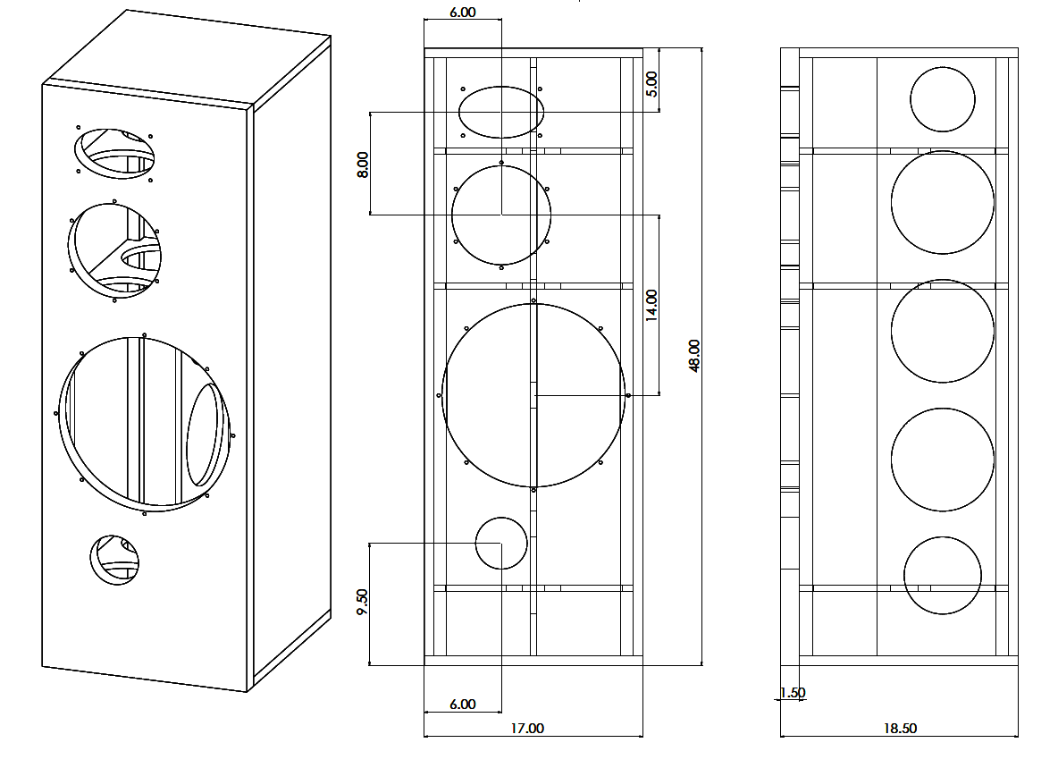
second attempt.
i lowered the drivers, now the HF s not that close to the top edge, I also offset the mid/hf from the center, and replaced 2" slot port on the bottom to a 4" port right under the woofer and offset from center (same distance as the mid/hf), no separated chamber for the mid section yet, i m still working on this, but so far what LineSource suggested (SBA cabinet) looks easy enough, we can talk about the mid section later, what do you think of the changes so far ?
Matthias: about the slot port vs round tube port, what made you switch to rear firing tube ? personal preferences, or one worked better than the other ? if i remember correctly we started with round port and then changed it to slot port design, I do not remember why tho.
Attachments

Last edited:
May need to change the 4" port to 6" (9" flare) or 2x 4" ports, Air velocity would be too high for single 4" port at high power.
second attempt.
i lowered the drivers, now the HF s not that close to the top edge, I also offset the mid/hf from the center, and replaced 2" slot port on the bottom to a 4" port right under the woofer and offset from center (same distance as the mid/hf), no separated chamber for the mid section yet, i m still working on this, but so far what LineSource suggested (SBA cabinet) looks easy enough, we can talk about the mid section later, what do you think of the changes so far ?
Did you model the diffraction of the tweeter and midrange on your baffle? Did you try different driver positions?
If you'd move the tweeter and midrange to the right by 0.5" (6.5" from the left edge), their left/right ratio would end up pretty much at the golden ratio. Also, the top/left ratio for the tweeter would end up at the golden ratio if you'd change the horizontal distance of the tweeter to the top edge to 4". But I might be too obsessed with the golden ratio thing.
Matthias: about the slot port vs round tube port, what made you switch to rear firing tube ? personal preferences, or one worked better than the other ? if i remember correctly we started with round port and then changed it to slot port design, I do not remember why tho.
Short summary (as I see it; others had different lines of thinking):
we started with a slot port on the front, at the bottom of the box. The bass tuning was right, but it leaked a lot of low upper bass / low midrange from the inside of the box, which wasn't good.
Some guys suggested to move the port closer to the center of the box (away from the bottom) because the port likes to couple to the pressure nodes of the internal box resonances (standing waves). The port supposedly couples much less to the standing waves if the port opening is near the nodes of the particle velocity. The first mode of standing waves has its minimum pressure (and highest particle velocity) at the center of the box. This was the reason to move the port opening to the center of the box. With the Monkey Coffin, the higher modes of standing waves are hardly relevant, because they are above the xover pass band of the woofer.
Since there was simply no space on the front for a port near the center of the box, the port had to go to the rear. Also, the residual upper bass / low midrange leakage is less of a problem if it is radiated from the rear of the box instead of from the front.
If was relatively easy to install both port options in my prototype box, and then seal one of the two in order to compare them. My listening tests showed that I preferred the sound with the centered port on the back over the bottom port at the front. The sound was cleaner. Measurements confirmed that there were less resonance issues from the centered port than with the bottom port.
That said, I'd suggest to keep the port away from the bottom (or the top) of the box.
You might also want to avoid the standing wave between the top and bottom panel of the box. With an internal height of approx. 47", the first mode will be at about 144 Hz, and there will be few higher modes (harmonics) within the pass band of the woofer xover. You don't want those leaking through the port. One way to reduce (avoid?) those modes would be to slant the top end of the woofer box in order to avoid the parallel top and bottom ends of the woofer box. Maybe you can separate the midrange volume with a slanted divider going from just below the midrange on the front to the rear upper end of the enclosure?
Last edited:
My few prototype tests are along what mbrennwa said. Try to keep few of the lowest enclosure dimension related standing waves, that are in or close the woofer pass band, not leaking through the port. Worst place for a port, with a woofer that plays high relative to box dimensions so that standing waves are within pass band, would be near any surface of the box walls since it is all pressure nodes of standing waves there and "leakage" is certain 🙂
Simulating in hornresp suggests that the height related (lowest) standing wave can be cancelled in the box if the woofer was midway of the frontpanel. Next harmonic to that (second lowest) has velocity node at 1/4 of the height and a port would "leak" the least of that if placed there. I suppose similar leakage could be had with port midway and woofer 1/4. Anyway, port entrance near a wall seems to have worse leakage than almost anywhere else.
My proto box is set up woofer 1/2 way port ~1/5, and the worst peak seems to be with the front-to-back standing wave (front firing ports), around 4-500hz if I remember.. Got some attenuation on that by perforating the ports, but not sure if it is necessary since it is an octave up from crossover frequency and might be detrimental on high power 🙂
Put at least two 4" ports, allows some tuning between in room response and power handling and chuffing sound.
Last edited:
Thanks for the tips,
a few thoughts, placing the woofer in the middle of the baffle is not possible since it will push the mid/hf all the way to the edge, but i ll try to place it as close to the center as i can or place the ports close to the center.
making the bottom and the top un parallel should be possible, but i came across this approach to avoid standing waves:

one side is covered with triangle (or half round) shape and the opposite side is covered with something like roofing material or some other absorbent material.
what do you think of that ?
a few thoughts, placing the woofer in the middle of the baffle is not possible since it will push the mid/hf all the way to the edge, but i ll try to place it as close to the center as i can or place the ports close to the center.
making the bottom and the top un parallel should be possible, but i came across this approach to avoid standing waves:
one side is covered with triangle (or half round) shape and the opposite side is covered with something like roofing material or some other absorbent material.
what do you think of that ?
Attachments
^Zero effect! What will be xo-frequency? Think about wavelength at and below that... and even 1-2 octaves above.
Welcome to compromise land 😀
Standing waves inside the box: there is not a structure you can put in there (in these low frequencies), that would prevent them happening. Wavelengths are so long, that any helpful structure would not fit inside the enclosure. For example divider panels, they only make the longest path (cabinet height) "path" longer and lower the frequency of a standing wave making it more problematic (more into pass band). Absorbing standing waves with stuffing is about the only "easy" solution. Some internal resonant structures might help but they take additional volume inside the enclosure and are more construction work.
It is a compromise to use reflex port with a driver that needs enclosure big enough to have standing waves in the pass band. So, if must use a reflex port with a big cabinet and can't exchange that to another compromise (driver and port position), just have to live with it. Might turn out the mid range leakage from the port(s) are not a problem at all 😉 After all, people have build such boxes and for example I've seen this http://www.humblehomemadehifi.com/download/Humble Homemade Hifi_Calpamos.pdf referenced in this forum on multiple occasions.
The big enclosure a PA driver needs is a bit of a compromise at home listening levels... One could make the three-way 15" sealed, choose a driver that doesn't need huge box, and use separate proper sub woofer to really impress friends. But, considering the design constrains here maybe just build the box you are building, just don't put the port next to the enclosure wall 🙂 Check out port position here The Loudspeaker - Jantzen-audio.com or any classic JBL big box for example.
ps. I'm almost convinced, that in my particular use case at home, I have to build the mid+tweet separate from the bass bins instead of one big box three way for this and another more important reason: I'm forced to put the speakers flat against a wall, can't get proper toe in with bulky enclosures! a small top box can be rotated easily for optimal listening triangle 🙂 No, won't use smaller than 15" for kicks!
Last edited:
Waste of time, effort and enclosure volume. Bracing it properly would do far, far more to benefit the sound.but i came across this approach to avoid standing waves:

one side is covered with triangle (or half round) shape and the opposite side is covered with something like roofing material or some other absorbent material.
what do you think of that ?
Thanks for the reply guys,
I made some changes to the drawing, i pulled the woofer almost to the center of the baffle (23" from the bottom instead of 24") and the ports 1/4" baffle height from the bottom.
in the Troel link you sent and almost all the classic JBLs the ports is close to the wall, which I don't get, maybe the cross over is lower than the first mode ? (here is 300Hz)
anyhow I tried to implement all the suggestions so far into this drawing, let me know what you think.
having the separated mid section is still puzzling me, with Q of 0.5-0.6 the volume for the TD8M is about 2-4 liter (winisd) which is way too small to do anything with other than a regular stuffed box around it.
Also having one of the top or bottom angled is a challenge to keep everything simple and easy.
Attachments
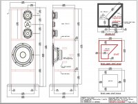
Why not making a tapered enclosure between front and backside and two horizontal bracings, see attached drawing.
The enclosure volume for this 8 inch midrange should be not less than 10 litres to keep the system resonance lower than 100 Hz, if possible.
For example, choosing the internal width at the front side 22 cm and 5 cm at the back side and the height about 22 cm, the volume becomes 13 L.
An option can be added to make the midrange enclosure open at the back side to try out an aperiodic cabinet also. Some midrange drivers do sound better (or different) if the cabinet is left open.
Attachments
Last edited:
- Home
- Loudspeakers
- Multi-Way
- Open Source "Tower XL"