In the ESP website schematic, the shield should be connected to the chassis, not to the audio circuit common (ground).
You mean like this (From ESP website):
An externally hosted image should be here but it was not working when we last tested it.
Yes, but it uses an opamp. We want SE Class A output.
That's what we call a ground-compensated or ground-cancelling output. It gives most of the benefits of a balanced output without the need for a balanced input at the receiving end.
Has never really caught on- I don't know why as if properly implemented a GC link is quieter than a balanced link and uses two opamps instead of three. (for the whole link)
Perhaps people don't like the idea of one pin of an XLR output being in reality an input.
Schematic in post #19 is wrong, I do not know where it came from.
Here is a correct schematic from ESP web site:
No need for R4 C1.
In post #18, I said: To go balanced from Single ended only takes 1 Op-amp and 2 resistors: This is U1B and R2 R3 in the above circuit. I mentionned 47 ohm resistors, these are R5 R6 with 100 ohm, values just as good.
As said, shield ground is chassis ground XLR pin1. Should be separated from circuit ground.
Simple....I do not see why not use an Op-amp and reinvent the wheel with a bunch of components.
Here is a correct schematic from ESP web site:
No need for R4 C1.
An externally hosted image should be here but it was not working when we last tested it.
In post #18, I said: To go balanced from Single ended only takes 1 Op-amp and 2 resistors: This is U1B and R2 R3 in the above circuit. I mentionned 47 ohm resistors, these are R5 R6 with 100 ohm, values just as good.
As said, shield ground is chassis ground XLR pin1. Should be separated from circuit ground.
Simple....I do not see why not use an Op-amp and reinvent the wheel with a bunch of components.
It came from same place you got the above schematic. It’s a “ground compensated” circuit.
It may be simple to use 2 or 3 opamps, each with maybe 12-14 internal transistors, but that’s technically more components than two transistors and a handful of resistors and caps. This circuit may not achieve ultimate low THD like the opamps, but sonically it sounds great as you can see from the harmonic distortion profile. Dominant 2nd order and descending higher orders. Having only two transistors - it is inhenertly very quiet. It doesn’t demand a quiet power supply though as do most single rail single ended Class A circuits.
It may be simple to use 2 or 3 opamps, each with maybe 12-14 internal transistors, but that’s technically more components than two transistors and a handful of resistors and caps. This circuit may not achieve ultimate low THD like the opamps, but sonically it sounds great as you can see from the harmonic distortion profile. Dominant 2nd order and descending higher orders. Having only two transistors - it is inhenertly very quiet. It doesn’t demand a quiet power supply though as do most single rail single ended Class A circuits.
Who cares about how many transistors are inside op-amp chips. What matters for me is the amount of work, cost and filling the requirement.
How many solder joint matters more than what is inside chips.
Why reinvent that works, is well designed and performs well ?
As said, for ultimate performance there exist integrated circuits optimized to drive balanced lines. That Corp 1606/1646 for instance.

THAT Corporation 1606/1646 OutSmarts Balanced Line Driver ICs
How many solder joint matters more than what is inside chips.
Why reinvent that works, is well designed and performs well ?
As said, for ultimate performance there exist integrated circuits optimized to drive balanced lines. That Corp 1606/1646 for instance.
THAT Corporation 1606/1646 OutSmarts Balanced Line Driver ICs
I doubt there will be answers.
Balanced Line Driver ICs:
THAT1646
Texas Instruments DRV135
Analog Devices SSM2142
Balanced Line Driver ICs:
THAT1646
Texas Instruments DRV135
Analog Devices SSM2142
I like 1646 too but you seem to miss the point of this thread: the simple elegance of the circuit and the nature of the harmonic profile it provides is second order and it is single ended class A. Sure, we all know how to go and get a THaT1646 or equivalen tcrom Burr Brown for a balanced line driver. Your point had been made - yes opamps can do this - but they are not the same thing.
I have given you this answer several times now and you persist.
The opamps do not have a 2nd harmonic dominant distortion profile since they are not SE Class A. They may be lower in THD, but oftentimes have a third order harmonic distortion that is dominant.
I do and so does Hugh, I believe.
Similarly, you might ask the folks SS forum why they don’t just use Chipamps vs discrete 8 or 9 transistor power amps.
I have given you this answer several times now and you persist.
The opamps do not have a 2nd harmonic dominant distortion profile since they are not SE Class A. They may be lower in THD, but oftentimes have a third order harmonic distortion that is dominant.
Who cares about how many transistors are inside op-amp chips.
I do and so does Hugh, I believe.
Similarly, you might ask the folks SS forum why they don’t just use Chipamps vs discrete 8 or 9 transistor power amps.
Last edited:

You are starting to sound more like a preacher or salesman than a Tech/EngineerI like 1646 too but you seem to miss the point of this thread: the simple elegance of the circuit and the nature of the harmonic profile it provides is second order and it is single ended class A. Sure, we all know how to go and get a THaT1646 or equivalen tcrom Burr Brown for a balanced line driver. Your point had been made - yes opamps can do this - but they are not the same thing.
Baited irrelevant question.Similarly, you might ask the folks SS forum why they don’t just use Chipamps vs discrete 8 or 9 transistor power amps.
No high power chip amps to begin with while discrete can give you anything, is that enough for you?
When I started with this , transistor books (think Philips, RCA, Texas, etc.) offered tons of DISCRETE amplifiers,in the range from 250mW 😱 to 1W, 1.2W,1.8W,etc. , meant for reciord players, radios, etc.
They were all SWEPT away by chipamps and nobody uses them any more.
The opposite has not happened with higher power amps ... yet.
But it´s basically a power, voltage and dissipation problem.
Couple that to Audiophiles being "classic" and "conservative"
The instant we have a wide choice of 25W to 300W chipamps at low cost, discretes are doomed also there.
That's what we call a ground-compensated or ground-cancelling output. .... Has never really caught on- ....
Was used on a professional dBx limiter. With boosted rails and discrete module.
The one opamp scheme, at usual supply voltages, can give +20dBu. Another half a 19 cent chip makes that +26dBu. Clearly this is a "better" spec, and the +20dBu box will lose customers.
While _I've_ never needed over +20dBu on a line, note that with conventional +4dBu levels a +20dBv clip gives only 16dB headroom, which is marginal in re-re-recording, especially since this is a *hard* clip. 18dB headroom reduces the occasional "awk" to hardly-ever. The 2-opamp plan gives 22dB headroom, so even needle-bangers hardly ever clip.
Of course recognizing that we never drive outside lines anymore, and that -10dBv is a fine level around the room, would kill this problem cold. But for many users it is all more-more-more.
This was my question in post 8 : Why not using That Corp 1606/1646 ?
Marc,
Let me list the reasons:
1. Far less active devices than an IC implementation
2. About the same cost
3. No global feedback with implications of harmonic profile
4. Something different.........
I understand the concern about something unconventional. This is the perennial criticism of any new idea, particularly in a world of cheap chips. But there is no suggestion you or anyone should use this idea, it is simply a new way of doing the old, and it does force one to go back to the basic principles which never does any harm. It is not a threat; more, it is an invitation to see it another way, like or not, nothing more. After all, if you reject this idea, you would never know if #3 is true or false. The fb issue has been argued hotly for about fifty years now and unlikely to be resolved now!
Hugh
No, you are wrong, I am not arguing. I'm stating a response to Marc's reasonable request, and your statement is not supported and was not asked for.
HD
HD
You are starting to sound more like a preacher or salesman than a Tech/Engineer
Baited irrelevant question.
No high power chip amps to begin with while discrete can give you anything, is that enough for you?
When I started with this , transistor books (think Philips, RCA, Texas, etc.) offered tons of DISCRETE amplifiers,in the range from 250mW 😱 to 1W, 1.2W,1.8W,etc. , meant for reciord players, radios, etc.
They were all SWEPT away by chipamps and nobody uses them any more.
The opposite has not happened with higher power amps ... yet.
But it´s basically a power, voltage and dissipation problem.
Couple that to Audiophiles being "classic" and "conservative"
The instant we have a wide choice of 25W to 300W chipamps at low cost, discretes are doomed also there.
Not going to argue that for someone to use SE Class A designs because of their inherent harmonic distortion profile, isn’t totally logic based on ultimate low THD, but psychoacoustics isn’t really logical is it? In the end, we listen to what we think sounds good. Like Aksa said, it’s something different and we are not saying it’s something everyone has to like.
Regarding high power chip amps - one could parallel them as has been done by numerous people to scale up the power. I am not opposed to chipamsp or opamps in general of course, and they have their place. My latest project uses them:
I just scaled up 8x OPA1622 headphone amp chips for a headphone amp that doubles as a low power speaker amp. 150mA x 8 is 1.2A - not bad for four 3mm square VSON10 packages.
Attachments
Last edited:
I would be interested to know which limiter. The GC concept has always intrigued me and I would like to find out who discovered it and when.Was used on a professional dBx limiter. With boosted rails and discrete module.
The one opamp scheme, at usual supply voltages, can give +20dBu. Another half a 19 cent chip makes that +26dBu.
True enough, the dynamic range of the balanced link is increased by 6 dB. No question there. However, even allowing for that, a link composed of a GC sense amp and a simple unbalanced line receiver can still be quieter, because a balanced input amp is a relatively noisy item. I bang on at length about this in Small Signal Audio Design; there are ways to tackle it.
...OPA1622 headphone amp chips[/B][/URL] for a headphone amp that doubles as a low power speaker amp. 150mA x 8 is 1.2A - not bad for four 3mm square VSON10 packages.
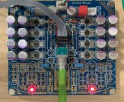
XKR, can you tell us about the that stuffed PCB?
The SMD placement and soldering appears to have been done by automation. If that is so, did you utilize some commercial service? If so, please share the pertinent details such as, vendor name, cost, min. quantity, etc. The challenge of hand placing and soldering finer pitch SMDs is limiting my DIY efforts. An cost effective hobbyist solution to that problem would be a real boon
Thanks.
You mean like this (From ESP website):
An externally hosted image should be here but it was not working when we last tested it.
Yes, but it uses an opamp. We want SE Class A output.
Aaargh...
Use 4-wire Calvin connection with active CMRR rejecting based on fully-differential opamp and active Vocm drive from the input of the next block.
https://www.diyaudio.com/forums/solid-state/320727-opamp-common-base.html#post5435606
XKR, can you tell us about the that stuffed PCB?
The SMD placement and soldering appears to have been done by automation. If that is so, did you utilize some commercial service? If so, please share the pertinent details such as, vendor name, cost, min. quantity, etc. The challenge of hand placing and soldering finer pitch SMDs is limiting my DIY efforts. An cost effective hobbyist solution to that problem would be a real boon
Thanks.
Hahah, that was assembled by the “xrk971 model 2000” pick and place machine and soldering was accomplished with a $10 dorm room hot plate and skillet from the bottom and a $50 hot air pencil from the top. I use Pb-Sn solder paste (MG 63-37, I think) applied with a syringe and hypo needle. Parts placed with good pair of Swiss Technitool tweezers and vision provided with flip up magnifying goggles. Those are 1210 resistors and 0805 caps - they are child’s play compared to 0402. The VSON10 packages look hard (but not really) have an underbelly pad and hidden pins. The solder surface tension self aligns them. Same with the rest of the parts. Trick is to apply just the right amount of paste (sparingly). Heat the skillet at medium to low heat and monitor PCB temp with IR thermometer. When it hits 130C and stabilizes, use 300C hot air pencil from above to liquify just the components of interest. Keep liquidus for at least 10 seconds and then go to next section. This way, parts only experience long term 120C to 150C and short term just long enough to melt and make a nice joint.
On complex jobs with lots of parts, I use a digitally controlled solder paste dispenser (i-Extruder) to lay down repeatable perfect size blobs even on 0402 and 0603 parts and skinny little 0.3mm pitch pins on a quad flat pack DSP chip. Your hand would cramp if you had to use a syringe on more than 30 parts.
It takes some practice of course - watch YouTube videos from SparkFun on SMT soldering and you can learn a lot. There is a lot of Pb-free solder paste out there - I prefer lead for its better flow and durability and lack of Sn-whiskers. Copper braid and thin free flowing liquid flux with a regular soldering iron chisel tip is your friend for removing excess or cleaning up solder bridges.
In the end, it’s much faster than TH soldering as everything is on one side and there is no clipping of leads or bending of leads needed.
Those tweezers seem expensive - but very crucial as they are your fingertip extensions and cheap ones just don’t work. I have had mine for 20 years. You have links above to just about everything you need to do this.
I have been eyeing a binocular stereo microscope workstation for some time now. That would be the next step and enable 0402 assembly much easier.
Essentials to get started: tweezers, magnifier goggles, solder paste, hot plate. Add hot air pencil later. Copper braid and flux might be handy and useful for TH soldering as well.
Hope that helps. Maybe another Howto thread is in order?
Last edited:
I would be interested to know which limiter....
dBx has made WAY too many limiters.
Memory said "160" but that is mono. The 165 is the stereo, has the right knobs/meters, but the plan I found is simple single-ended.
DBX 165 - Manual - Over Easy Compressor / Limiter - HiFi Engine
Mine had a later manual (pamphlet instead of binder). This would be early-mid 1980s.
They boxed the same stuff several ways, and probably had several revisions of each model. I found the impedance-balanced plan in the 160:
DBX 161 - Manual - Single Channel Compressor / Limiter - HiFi Engine (manual covers 160 and 161)
Note also not simple impedance balanced, but a "hum sense" resistor and differential NFB. (as in post #37 here) So not the same thing. Sorry for the false trail.
Attachments
Last edited:
Hahah, that was assembled by the “xrk971 model 2000” ...Hope that helps. Maybe another Howto thread is in order?
Impressive for manual work.

- Home
- Source & Line
- Analog Line Level
- Making balanced output from single end