Thanks Jan for answering this quick!
Is there any preferred opamp which is capable of +/-36V?
I tried to read all the 160+ pages, but it's a lot to read.
What kind of zener do you prefer for 60V regulated output?
Many thanks and cheers! (hmm, it's a bit early for a Bernardus Abt 🙂 )
Alex
I'm not familair with high voltage opamps, but the OPA454 and ADA4700 come to mind. Not sure they fit the PCB footprint.
If you mean the zener on the opamp output, should be half total supply, but not critical. Only necessary to keep the opamp output away from ground and supply, so for 60V anything between 20 and 40V would work..
Jan
Thanks Jan, looking at datasheets of those opamps, they have rather high noise rates.
What are, in your opinion, the most important characteristics to look for in a suitable opamp in this design?
I haven't a clue what to look for, bandwidth, slew-rate, Noise, Unity gain, cmrr, etc?
Sorry for asking these questions, but I really haven't a clue 🙁
What are, in your opinion, the most important characteristics to look for in a suitable opamp in this design?
I haven't a clue what to look for, bandwidth, slew-rate, Noise, Unity gain, cmrr, etc?
Sorry for asking these questions, but I really haven't a clue 🙁
Hi Patrick, I noticed that one too, specs seems great to me, but again, I haven't a clue if they are good for this design. If I am not mistaken, Jan did not like this one for regulator design
Trust Patrick to find some exotics! ;-)
Spec-wise this looks good, the problem with this one is that it is hardly diy-solderable.
The ADA4700 is solderable, as is the OPA545. In this app the back plane soldering can be omitted, just put some thermal grease.
Slew rate is not that important, the output barely moves. Low noise is nice, wide bandwidth is nice. Ohh and unity-gain stable preferably...
Jan
Last edited:
Ok, thanks a lot Jan, and Patrick too 🙂
I soldered NDK NZ2520SD XO's by hand, they measure 2.5x2.0mm only, these ADHV4702 measure 7x7mm, they are big, hahaha 🙂
Maybe I will try them, or get some soldered to brown-dog adapter or other.
Cheers!
I will try LTC6090-5 first, 24m bandwith, 14n noise, little bit easier to solder
I soldered NDK NZ2520SD XO's by hand, they measure 2.5x2.0mm only, these ADHV4702 measure 7x7mm, they are big, hahaha 🙂
Maybe I will try them, or get some soldered to brown-dog adapter or other.
Cheers!
I will try LTC6090-5 first, 24m bandwith, 14n noise, little bit easier to solder
Last edited:
"The LTC6090 is unity gain stable. The LTC6090-5 is stable in noise gain configurations of 5 or greater"
Can I use the -5 version or not? If not I definitely will go for ADHV4702
Can I use the -5 version or not? If not I definitely will go for ADHV4702
"The LTC6090 is unity gain stable. The LTC6090-5 is stable in noise gain configurations of 5 or greater"
Can I use the -5 version or not? If not I definitely will go for ADHV4702
It's hard to say, there's a lot of gain in that loop, and for sure don't use the -5. You probably can compensate externally but without some pretty good scope and knowing what you do its hard. This is also for me uncharted terrain.
Personally I would give the 6090 a try.
Jan
On the BOM, the voltage divider resistors are specified as 1K, 0.25W metal film. Higher dissipation, better temco resistors are better (if you can fit them!).
Especially with 60V, you need to recalculate the divider ratio of course, and there's much more voltage across the top R. P = E^2/R ;-)
Jan
Jan
On the BOM, the voltage divider resistors are specified as 1K, 0.25W metal film. Higher dissipation, better temco resistors are better (if you can fit them!).
Thanks! I will keep that in mind when ordering all components!
Especially with 60V, you need to recalculate the divider ratio of course, and there's much more voltage across the top R. P = E^2/R ;-)
Jan
Of course I'll have to recalculate 🙂
About the "Top R", meaning? And, I suppose E=I (Amperage) 🙂
Last edited:
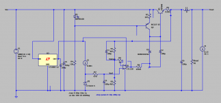
Have been playing with spice model for a sulzer style superreg; I did ac sweep with the current source load as the AC source, and plotted output voltage to see the load regulation.(not sure if it's correct, maybe the metaphysics probes are connected wrong, since its loop gain that should be shown here)
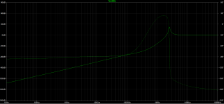
There is always a peak in the frequency response @ 2-5MHz, depending on the pass transistor used in simulation, and cannot be mitigated by tinkering with compensations like ESR Zero, bypass capacitor in the negative input of error amp. Using feedforward compensation caps at error amp even make this peak higher😕 adding a small resistor to the emitter reduces this peak to ca. 6dB, at the cost of worsen performance at low frequency.
Could anyone kindly tell me where the problem is?
Attachments
Last edited:
I think the opamp is dominant here. Have you tried with different opamps?
How high is the peak?
Jan
How high is the peak?
Jan
Hi Jan,I think the opamp is dominant here. Have you tried with different opamps?
How high is the peak?
Jan
yes I did. 797 and 49710, as well as some random stuff from ltspice library. It seems as if the transistor has much more effect on the amplitude, varying from 5dB to almost 20dB in the picture. With slower opamps the peak is mostly gone, but still it's strange since 49710 is stable in the real application, and 797 oscillates at 770kHz according to jacknini in the previous posts. AND lt1028, which is theoretically unsuitable for the job, shows lower peak than 1128....
...and 797 oscillates at 770kHz according to jacknini in the previous posts. AND lt1028, which is theoretically unsuitable for the job, shows lower peak than 1128....
it oscillates in response to where it is excited. in my case 770kHz is the frequency of a 50kW AM station nearby.
you can use Zout for measuring stability. the "Q" of the impedance peak is related to phase angle. when you draw the impedance, it's simply Vout/Iout in "Add Traces"
also -- for consistency's sake -- i.e. to be comparable to the impedance charts in Walt's article -- use the same excitation current (50mA if i recall.) when you use a large current the pass transistor's gain increases.
About the "Top R", meaning?
And, I suppose E=I (Amperage)
The larger R (upper R on the diagram), connected to the positive voltage.
E (Electromotive force) = V = voltage
Last edited:
Hi Jan,
yes I did. 797 and 49710, as well as some random stuff from ltspice library. It seems as if the transistor has much more effect on the amplitude, varying from 5dB to almost 20dB in the picture. With slower opamps the peak is mostly gone, but still it's strange since 49710 is stable in the real application, and 797 oscillates at 770kHz according to jacknini in the previous posts. AND lt1028, which is theoretically unsuitable for the job, shows lower peak than 1128....
You'd want an opamp with a much wider bandwidth than the pass resistor, or the opposite. You'd want to avoid similar bandwidths which would put the two phase shifts right on top of each other.
Jan
it oscillates in response to where it is excited. in my case 770kHz is the frequency of a 50kW AM station nearby.
you can use Zout for measuring stability. the "Q" of the impedance peak is related to phase angle. when you draw the impedance, it's simply Vout/Iout in "Add Traces"
also -- for consistency's sake -- i.e. to be comparable to the impedance charts in Walt's article -- use the same excitation current (50mA if i recall.) when you use a large current the pass transistor's gain increases.
Hi Jacknini,
thanks for pointing out that! Will try measuring Zout tonight, with different ops..Are there any other parameters that could potentially describe the stability of a SR?
that sounds similar to Pole-splitting! Will buy some high Ft Tubes...You'd want an opamp with a much wider bandwidth than the pass resistor, or the opposite. You'd want to avoid similar bandwidths which would put the two phase shifts right on top of each other.
Jan
- Home
- The diyAudio Store
- Super Regulator