What I notice on my setup was that with PP capacitors I had a slight sibilance on female voices with the 'S' being also kind of 'muddy'. With polystyrene caps, the sibilance is gone, the 'S' sounds natural and clean. They will stay in there definitely.
Schematic
Hi Ronny, I want to try your inverse RIAA schematic and I want to know how critical is the value of C1-2n26 (2260pF). I have a couple of 2n2 1% capacitors in hand I was wondering if I can use them. Thanks.
If you can measure capacity, select the two which are nearby the value.
If not i can look if i have 2 capacitors left over to send or maybe i have complete PCB with all parts.
Please then contact me at PM.
2n2 will also do fine.
Ronny
If not i can look if i have 2 capacitors left over to send or maybe i have complete PCB with all parts.
Please then contact me at PM.
2n2 will also do fine.
Ronny
Attachments
Last edited:
...how critical is the value of C1-2n26 (2260pF). I have a couple of 2n2 1% ....
It is a 2.7% error and can cause a 0.24dB response difference. Small, but I have seen golden-ears say 0.25dB is audible.
Why not add a 60pFd in parallel? Because it is a small correction, this does NOT have to be a high precision capacitor. A 20% part is fine. A 56pFd part is plenty close enough.
It is a 2.7% error and can cause a 0.24dB response difference. Small, but I have seen golden-ears say 0.25dB is audible.
Why not add a 60pFd in parallel? Because it is a small correction, this does NOT have to be a high precision capacitor. A 20% part is fine. A 56pFd part is plenty close enough.
Thank you for explanation. I will probably do like you suggested, add 56pF in parallel. Mouser, digi-key has plenty in stock.
I can give you the gerber files. The design was made in Sprint Layout.
Hi flancfuster, if possible, I´d like the Gerbers as well. I´ll PM you with the e-mail address. 🙂
With a big thanks to Koifarm for allowing copy´s and sharing, and same thanks to flancfuster for sharing his files, I had some PCB´s made.... MM Mini-Me and PSU.
My first intention was to give some away, but they ended up a little more costly than expected + they got "caught" in customs :-(.
I´ll start a thread in "swap meet".
https://www.diyaudio.com/forums/swap-meet/337643-mini-mm-phono-pcb.html#post5784650
My first intention was to give some away, but they ended up a little more costly than expected + they got "caught" in customs :-(.
I´ll start a thread in "swap meet".
https://www.diyaudio.com/forums/swap-meet/337643-mini-mm-phono-pcb.html#post5784650
All the thanks should go to Koifarm, who supplied the scheme, and flancfuster, who did the layout. All I did was to ask for the gerbers and order more PCB´s than I needed. The surplus went to you guys 🙂
I hope Koifarm will agree with me, that the best place would be before the output. Twist the tube so the "not matching" sector will be the cathode (output) follower (V2b).
The reason: Cathode follower lowers the output impedance and only has gain of 1 (or a little less) = least or no impact 🙂
Thats what i also would do.
Please use Mini-me thread for this kind of questions. Then other builders can also share this experiences.
Since board and tubes are here, time to think about parts, starting with psu..
(ah, yes, board are really nice, but, as Boydk said, some alternative holes would be nice, for easy fit of WIMA MKP capacitors, but we will manage somehow..).
Anyway, any suggestion for adequate transformer?
I guess there is no reason to mount C1 and C2 on bottom side except aesthetic? (as seen on photos some pages before). In that case, one might mount all electrolytic on bottom side, leaving tubes and some nice looking capacitors on top 🙂
Thanks!
Tommy
From boydk,
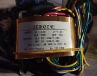
My source:2N1357 voedingstrafo voor buizenversterkers 48VA
I got mine made a little smaller. Wrote an E-bay seller if he could get them made, and yes, 5-7 workdays, so guess he´ll be shipping them about now.
PRIM 0-115, 0-115
SEC 0-120v 40mA
0-120v 40mA
0-6,3v 1,2A
0-6,3v 1,2A
I ordered 5 pcs. and got them for 25$ a piece.
https://www.ebay.com/str/along1986090
My source:2N1357 voedingstrafo voor buizenversterkers 48VA
Hi Tommy,
For cheaper option on coupling capacitors I suggest Solen MKP Fastcap. They have long leads and are quite good. C1, C2 were mounted on bottom to keep them away from tube radiating heat. I realized that after the PCB was made. Just to let everyone know that this was my first PCB layout design. I've had help from AlexMM. The design was made to fit my parts and was not made for multiple options.
For cheaper option on coupling capacitors I suggest Solen MKP Fastcap. They have long leads and are quite good. C1, C2 were mounted on bottom to keep them away from tube radiating heat. I realized that after the PCB was made. Just to let everyone know that this was my first PCB layout design. I've had help from AlexMM. The design was made to fit my parts and was not made for multiple options.
Since board and tubes are here, time to think about parts, starting with psu..
(ah, yes, board are really nice, but, as Boydk said, some alternative holes would be nice, for easy fit of WIMA MKP capacitors, but we will manage somehow..).
Anyway, any suggestion for adequate transformer?
I guess there is no reason to mount C1 and C2 on bottom side except aesthetic? (as seen on photos some pages before). In that case, one might mount all electrolytic on bottom side, leaving tubes and some nice looking capacitors on top 🙂
Thanks!
Tommy
My build is running, no time to test but it runs at 160V with 11mA per side. Heaters seem to only consume 760mA for all four, spec suggests 400mA? They look just fine and run at 200mA if at 12.6V. Onto the scope tomorrow!


Please don't pay attention to the wiring, its just for checking basic function, insulating sleeves etc still in the post.
Please don't pay attention to the wiring, its just for checking basic function, insulating sleeves etc still in the post.
All measurements are oke. 2 x 2 heaters are good for 2 x 380ma = 760ma at 12v. So is 11ma a side.
My 2 cents for adjusting treble if you want more treble raise R1/R1a to 56k or 68k. For lower treble lower R1/R1a. But maybe you already know it.
My 2 cents for adjusting treble if you want more treble raise R1/R1a to 56k or 68k. For lower treble lower R1/R1a. But maybe you already know it.
Last edited:
Thanks for the reassurance Mr Koifarm, I am not an HF emphasis character so I'll be putting my SUT straight into the input when time comes to actual music, first off I wish to see the output on a scope. My intention is to kit the board out 'full fat' for MM compatibility, although I am probably a MC man at heart. Happy days ��
For best results using SUT I recommend reading below guide:
Moving Coil Step Up Guide – K & K Audio
I'm using Lundahl and the resistor in parallel made a big difference in tonality.
Moving Coil Step Up Guide – K & K Audio
I'm using Lundahl and the resistor in parallel made a big difference in tonality.
Thanks for the reassurance Mr Koifarm, I am not an HF emphasis character so I'll be putting my SUT straight into the input when time comes to actual music, first off I wish to see the output on a scope. My intention is to kit the board out 'full fat' for MM compatibility, although I am probably a MC man at heart. Happy days ��
I'm using Lundahl and the resistor in parallel made a big difference in tonality.
That´s the normal way of selecting the load impedance to suit your cartridge.
Others might even need a zobel network too for high frequency compensation:
Sowter Type 9990 1:20 Phono Cartridge transformer
The only ones i know, that don´t need it are my Silk Audio MC-220A:
SACThailand
🙂
- Home
- Source & Line
- Analogue Source
- Mini-Me phono preamp