My stereo pair has one in the corner, as you saw, and one on the wall far from corner. The baffle/drivers there are rotated also, unfortunately. Maybe not unfortunately - I think/hope it has less boundary interference that way even if I can't model it in Vituix.
I will content myself with looking at floor and ceiling reflections, without side or front wall reflections, as I plan absorption on walls next to the speaker. Results seem reasonable that way. With rotation and front and side wall reflections, need for absorption was clear and that tracks with what I've seen online.
I will content myself with looking at floor and ceiling reflections, without side or front wall reflections, as I plan absorption on walls next to the speaker. Results seem reasonable that way. With rotation and front and side wall reflections, need for absorption was clear and that tracks with what I've seen online.
Attachments
One more rotation parameter to VCAD could be useful because reflections from walls parallel and perpendicular to listening axis is not very common in practice. It's okay for simplified studies.
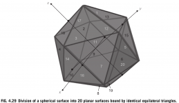
I've already mentioned Beranek & Mellow few times. Those guys represent simpler method which gives good result when pressure measurement directions are toward middle position of each sector.
Alright, I looked it up. I am not sure, but I believe you are referring to Figure 4.29 in the Mellow + Beranek book (screenshot attached). Given your earlier notes regarding the "weighting factors" and your confirmation of the Tylka formula, I don't see how the method implemented in Vituix could be the same as the "simpler Beranek + Mellow" approach. I am therefore left with the (somewhat vague) assumption that Vituix uses the formula described in the Tylka document, possibly with some (minor?) deviations that result in the slightly different power response curve (post 1187).
I still think the documentation should allow users to look up the methods implemented in Vituix so that they are able to understand what the software does -- but its your software, and your decision.
Attachments
One more rotation parameter to VCAD could be useful because reflections from walls parallel and perpendicular to listening axis is not very common in practice.
Rev. 2.0.16.1 (2019-05-07)
Main program
* Added Toe-in text box to Drivers tab for reflections.
Note that simulation of front wall reflection requires 0-180 deg data with Mirror missing on.
I was just going to say in response to your prior comment about needing one more rotation parameter that it sounds like you were working on something.
BTW, noticed that listening window doesn't follow reference angle entry
Hmm, with new rev my entries into left wall reflection distance box are being forced to zero. Correction: I can't enter small values reflecting corner placement but I can enter large values, consistent with not supporting corner location
In the directivity line charts with 1 deg directivity data, at what angles do you switch colors?
also noticed room response curve changes with reference angle, even with just floor and ceiling reflections included. just 1 degrees makes big difference. Maybe I shouldn't do that 🙂
whoops now even large left wall distnaces entries are being zeroed? Not sure what I was seeing before. I guess that is indication to just model mid wall placement
any chance for directivity chart showing the room response?
whoops now even large left wall distnaces entries are being zeroed? Not sure what I was seeing before. I guess that is indication to just model mid wall placement
any chance for directivity chart showing the room response?
Last edited:
I am not sure, but I believe you are referring to Figure 4.29
Not that one.
I don't see how the method implemented in Vituix could be the same as the "simpler Beranek + Mellow" approach. I am therefore left with the (somewhat vague) assumption that Vituix uses the formula described in the Tylka document..
Short history of power & DI in VCAD: In the beginning whole 0-180 deg with constant angle step was required to get decent result. Weighting was simple sin() - just like in example of Beranek & Mellow. Calculator tool still uses that method. 2nd generation was simple weighting with sin() but at the middle point of possible arbitrary sectors. Arbitrary angle steps and left/right asymmetry and shorthanded data was allowed. 3rd generation had integral of sine within each - possible arbitrary sector. Current implementation is area calculation of sphere (instead of integral of sine). Logic for sector limit detection was updated (better or worse, but at least more readable code). All of those give quite equal results, but flexibility has improved.
So calculation is not Beranek & Mellow or Tylka or any other wise guy or smart a**. It's by Saunisto (local idiot from countryside) with required workarounds to manage shorthanded data.
Now BACK OFF please. This won't help you to make decision should you measure some monkey speakers from rear or not.
any chance for directivity chart showing the room response?
Sorry, no chances.
BTW, noticed that listening window doesn't follow reference angle entry
That's right. That curve stays quite constant regardless is center at 0 deg or not.
..left wall reflection distance box are being forced to zero.
Left side wall X = -5000...0 mm. Earlier revision allowed positive values i.e. right side wall, but that would also require different sign for toe-in angle. Too complex for users. Dynamic layout image would help, but programming requires more time than I had this morning...
at what angles do you switch colors?
It's gradient (though looks quite stepping). You can control color slope with SPL span.
hi Mbrennwa
I'm interested in checking your most recent version of the matlab code from post #1162 which you mentioned has been updated in post #1187. Could you please upload the final version?
thanks!
I'm interested in checking your most recent version of the matlab code from post #1162 which you mentioned has been updated in post #1187. Could you please upload the final version?
thanks!
hi Mbrennwa
I'm interested in checking your most recent version of the matlab code from post #1162 which you mentioned has been updated in post #1187. Could you please upload the final version?
thanks!
I uploaded it to github. Take a look at the tylka.m file.
I wrote the code using GNU Octave, which is very similar to Matlab, but not a perfect clone in all details. Let me know if works with Matlab out of the box, of if modifications to the code are required to make it run smoothly with Matlab. I guess it's best to continue the discussion on github, as I was asked to "back off" in this thread.
Rev. 2.0.17.0 (2019-05-08)
Main program
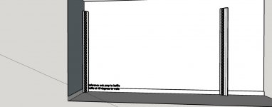
* Added Room tab including Reflection settings (previously in Drivers tab) and two images visualizing locations and reflection rays from top and left views.
Main program
* Added Room tab including Reflection settings (previously in Drivers tab) and two images visualizing locations and reflection rays from top and left views.
An externally hosted image should be here but it was not working when we last tested it.
Thanks for the room tab. It really helps visualize what is going on, but the visualizations bring up questions.
You show a ray going through the baffle to the front wall but clearly its got to diffract around the baffle to get to the front wall. At the least there is increased path length but also the question of the direction taken away from the baffle edge. I'm going back to back to the diffraction tool to see to what degree baffle width and edge profile affect the room response. Any hint as to what I will find?
Thanks,
Jack
^Ray is a bit confusing term, but idea is to visualize direction and distance from speaker's origin where reflected response is simulated before attenuation by absorption and summing to direct sound i.e. simulation result at the spot. We don't have X- or gamma-ray data in VCAD so no need to worry about passing the box more than actual measurement data includes 🙂
In previous screen shot image Listening distance=3000 mm (set in Options window) and Reference angle=+10 degrees => Image reflected from front wall is simulated at 4837 mm towards hor +141 deg off-axis from speaker's origin. Total gain of simulated reflection is 10^(-2/20)*3000mm/4837mm=0.49. Whole data with millions of details in that point is mirrored to listening spot assuming that sound reflection equals to perfect optical mirroring. That is just approximation of course.
In previous screen shot image Listening distance=3000 mm (set in Options window) and Reference angle=+10 degrees => Image reflected from front wall is simulated at 4837 mm towards hor +141 deg off-axis from speaker's origin. Total gain of simulated reflection is 10^(-2/20)*3000mm/4837mm=0.49. Whole data with millions of details in that point is mirrored to listening spot assuming that sound reflection equals to perfect optical mirroring. That is just approximation of course.
Last edited:
At the least there is increased path length but also the question of the direction taken away from the baffle edge.
Diffraction tool includes the shortest path length from driver around front baffle to virtual mic/listening point. It's not capable to produce partly flush mounted or half space response data. Responses to half space with directivity of ideal circular piston can be produced with Enclosure tool 1.1 (with angle step limit) or Calculator tool (which is slower to use). In addition, diffraction tool supports corners >>180 deg. Especially not angles <180 deg. Diffraction model was not designed for inner corners.
Dual channel measurement data (of single driver in prototype box) is much better than diffraction simulation. Any shape and mounting and efficient path lenght to rear are supported, and simulation of front wall reflection can be switched off. Reflections and far field measurement distance are the challenge and error source at home.
Last edited:
Hi Kimmo,
While working on a crossover I could not find a way to export the listening window response as time domain impulse.
(I wanted to do this to base a fir overall correction filter on)
The workaround I have used now is to export te directivity response and then average the listening window responses in the calculator tool and then using this response as as filter on a flat driver and then exporting the total spl, but this is a bit cumbersome 😀
Could you please add export of the listening window response as impulse response?
Many thanks again for your fantastic work!
Kees
...export te directivity response and then average the listening window responses in the calculator tool and then using this response as as filter on a flat driver and then exporting the total spl, but this is a bit cumbersome 😀
😀 😀 You've earned a medal for bravery. I will add few more exports to make this a bit easier.
Proposal for revision 2.0.18. What would you think about following?
* Folder structure changed to enable installation without adding user to administrators group.
Files installed to subfolders of \Users\Public\Documents\VituixCAD:
- Enclosure - local driver database (VituixCAD_Drivers.txt).
- Library - library blocks (.vxl, .png)
- Projects - response file samples (.txt)
- Template - LTspiceIV templates (.asc, .plt)
* Enclosure tools asks user to update local database if installed file in Public folder is older than file in user's folder. This copies driver data added by user with older versions to current database in Public folder.
Everything is done, but this has some drawbacks so I have delayed publishing. I can also cancel whole thing if this causes too much trouble.
🙂thank you!😀 😀 You've earned a medal for bravery. I will add few more exports to make this a bit easier.
^Listening window average to IR will have some technical issues. It is typically just an average of pressure magnitudes. Magnitude result will reduce due to delay/phase differences if we sum multiple pressures with phase information.
If we sum magnitudes without phase and use phase of calculated average or axial response, the result will not be necessarily minimum phase though reality would be. One method is calculating minimum phase for average and then adding excess phase of reference (axial) response, but it's too complex for this purpose imo, and axial could be set outside listening window. Cheaper trick would be selecting phase of some average off-axis angle.
If we sum magnitudes without phase and use phase of calculated average or axial response, the result will not be necessarily minimum phase though reality would be. One method is calculating minimum phase for average and then adding excess phase of reference (axial) response, but it's too complex for this purpose imo, and axial could be set outside listening window. Cheaper trick would be selecting phase of some average off-axis angle.
I like all the points. Love them. What drawbacks do you see?Proposal for revision 2.0.18. What would you think about following?
* Folder structure changed to enable installation without adding user to administrators group.
Files installed to subfolders of \Users\Public\Documents\VituixCAD:
- Enclosure - local driver database (VituixCAD_Drivers.txt).
- Library - library blocks (.vxl, .png)
- Projects - response file samples (.txt)
- Template - LTspiceIV templates (.asc, .plt)
* Enclosure tools asks user to update local database if installed file in Public folder is older than file in user's folder. This copies driver data added by user with older versions to current database in Public folder.
Will your auto update process now update the public driver database too? If yes, will it retain the entries created locally, and update only those which have been updated globally but not modified or created locally?
- Home
- Design & Build
- Software Tools
- VituixCAD