replacement 66 crossovers
Thanks moermusic
The website for the crossovers = Amocom (Speaker Crossovers) - Hand Built Premium Speaker Filters
There is a link to ebay where they are listed at 190 pounds.
Has anyone evaluated these?
Thanks moermusic
The website for the crossovers = Amocom (Speaker Crossovers) - Hand Built Premium Speaker Filters
There is a link to ebay where they are listed at 190 pounds.
Has anyone evaluated these?
Prelude to about the Measurements , and those ebay crossovers
Hello all ,
Something in this diy Audio website didn't send the usual email informing that someone had responded to my last Post ... usually a notification is sent , though occasionally one isn't , so I looked out of curiosity and found a whole new page of Posts !
Hi Doug ,
I know of those crossovers as someone else drew my attention to them as that maker also sells them on ebay.
I looked at them in detail on ebay.
If someone wants to buy those he makes for Tannoy loudspeakers , well they'll probably work OK , and hopefully well , but I am not a lot familiar with Tannoy crossovers , except that I very much prefer the Dual-Concentric Tannoy models when Bi-amped with the amplifiers driven by Active Crossovers ... as they usually are in Recording Studios ... but as this is a Celestion thread I'll not describe about Tannoys here.
I do not recommend those new crossovers for Celestion 44 and 66.
They look like they will work , and would give better sound than old crossovers with deteriorated capacitors ,
but the capacitor choices can be bettered ... unless a listener particularly like those capacitor combinations.
Primarily, the Inductors do not need to be replaced , as there is nothing substantially wrong with the original Celestion inductors.
If one wants the small benefits of modern manufacturing then better when changing the Inductors would be to use larger air-core inductors in the woofer circuit and first in midrange shunt circuit ,
because using Cored inductors introduces Saturation ... if you like the compression effects of saturated inductors OK your choice ,
but ... and I have posted plenty about that previously in this thread.
If you want lower DC resistance inductors in the woofer circuit to enable more output from the woofers and tighter control over the ABRs then go back to what I advised Reggie in this thread for lower resistance air-core inductors.
Do not change any of the inductors in the midrange or tweeter circuits , because better results can be achieved with those original Celestion inductors simply by making a new larger board and placing them all further apart in the manner I advised Reggie earlier in this thread.
I thought you had bought new Capacitors Doug ... what is case now with those ?
--- --- ---
Hi Denny G , and ToTo Man welcome !
ToTo Man ,
I have now read quickly through your two Celection threads in that other Forum , and I found several things there worth discussing , thus I'll return to that Forum when I have time available , and possibly join it and post about your topics there so that it is all in one place for whoever else may be following those threads.
I am very short of Time currently , thus for today I say that I will return when I have time available and explain those two Impulse Response plots you posted in this thread.
Denny ,
have you inverted the Polarity somewhere in your Test circuit for your new Impulse Response plots ?
or are those results in the actual Polarity -{ positive and negative connections }- that your drivers are in connected to the crossovers ?
Alternately , does your Amplifier invert Polarity ? ... and did you post the Reference Test Signal shape not though your amplifier ?
ToTo Man ,
Is the Horizontal Axis of those Plots in milliseconds ? or in metres ?
{ I can guess , but better is to ask to be sure.}
About your MF and MD 500 queries there and here ,
so far as I can understand from everything posted about both in this thread both are the same design , but it seems likely that Celestion upgraded either the Insulation of the voice-coil winding for the MD or upgraded the Adhesive used for connection of voice-coil to diaphram to a higher Heat tolerated type.
Either above would allow higher Power use.
Yes , as soon as one thing is changed in a design then it causes something else to change , and in the case of the MDs it seems that the new adhesive hardens over time more so than the original in the MFs and thus the scratching sound that one of the early contributors to this thread found in his MDs -{ though there could be another reason for that }.
Thus , if you have working MFs then keep them , as they may survive longer than MDs , and definitely if you do not overdrive them into too much Heat dissipation for their lower powered voice-coils.
There were always differences in Frequency Response for early model Dome drivers more so than for most Cone drivers , except for Cone Tweeters ,
because back then everything was hand assembled , and for otherwise manufactured parts the manufacturing Tolerences were not as close as can be achived with modern precision machinery.
One clue to assessing all your Mid-domes and Tweeters as to why some of the domes measure so much different to other samples can be seen if you do Impedance Plots for all your MFs and MDs and HF2000s.
If you can do complete Impedance and Phase plots then better , but if you can only measure Impedance then that will likely show sufficient ,
thus before you assemble any more complete systems or sell any drivers , do Impedance plots and post them either in this thread or in the other thread.
I have discussed Impedance plots in this thread with another member whose had some partially faulty domes.
For reference for buying parts , what nation do you live in ?
You haven't included a Flag with your member name.
I have to log off now , but I'll return when I have time available.
Hi Alan,
have you inverted the Polarity somewhere in your Test circuit for your new Impulse Response plots ?
or are those results in the actual Polarity -{ positive and negative connections }- that your drivers are in connected to the crossovers ?
The amp + would have been connected to the positive on the speakers, the red terminal.
Alternately , does your Amplifier invert Polarity ?
I don't know if there is an inversion there. I used a Sugden A28 amp. I see that REW has a setting to invert the input but this defaults to off.
... and did you post the Reference Test Signal shape not though your amplifier ?
The impulse responses are generated by the REW software from data recorded during the FR tests. I'm not an expert on REW so I don't know what it does with the Reference signal. Can you expand a bit on your question.
ToTo Man ,
I have now read quickly through your two Celection threads in that other Forum , and I found several things there worth discussing , thus I'll return to that Forum when I have time available , and possibly join it and post about your topics there so that it is all in one place for whoever else may be following those threads.
I am very short of Time currently , thus for today I say that I will return when I have time available and explain those two Impulse Response plots you posted in this thread.
---------------------------------------------
Is the Horizontal Axis of those Plots in milliseconds ? or in metres ?
{ I can guess , but better is to ask to be sure.}
About your MF and MD 500 queries there and here ,
so far as I can understand from everything posted about both in this thread both are the same design , but it seems likely that Celestion upgraded either the Insulation of the voice-coil winding for the MD or upgraded the Adhesive used for connection of voice-coil to diaphram to a higher Heat tolerated type.
Either above would allow higher Power use.
Yes , as soon as one thing is changed in a design then it causes something else to change , and in the case of the MDs it seems that the new adhesive hardens over time more so than the original in the MFs and thus the scratching sound that one of the early contributors to this thread found in his MDs -{ though there could be another reason for that }.
Thus , if you have working MFs then keep them , as they may survive longer than MDs , and definitely if you do not overdrive them into too much Heat dissipation for their lower powered voice-coils.
There were always differences in Frequency Response for early model Dome drivers more so than for most Cone drivers , except for Cone Tweeters ,
because back then everything was hand assembled , and for otherwise manufactured parts the manufacturing Tolerences were not as close as can be achived with modern precision machinery.
One clue to assessing all your Mid-domes and Tweeters as to why some of the domes measure so much different to other samples can be seen if you do Impedance Plots for all your MFs and MDs and HF2000s.
If you can do complete Impedance and Phase plots then better , but if you can only measure Impedance then that will likely show sufficient ,
thus before you assemble any more complete systems or sell any drivers , do Impedance plots and post them either in this thread or in the other thread.
I have discussed Impedance plots in this thread with another member whose had some partially faulty domes.
For reference for buying parts , what nation do you live in ?
You haven't included a Flag with your member name.
I have to log off now , but I'll return when I have time available.
Hi Alan,
Many thanks for the reply, I appreciate it, and I look forward to hearing more from you in due course, but let me answer your questions in the meantime:
- The impulse response x-axis is in milliseconds.
- I don't (think) I have the equipment to measure impedance plots. I'm still fairly new to all this stuff. In fact it's only fairly recently that I realised that DCR is a pretty useless measure of a driver's operational health and output efficiency. My measuring kit is basically a UMIK-1 USB mic and RoomEQWizard software, which allows me to make acoustic measurements to measure things like frequency response, harmonic distortion, phase, impulse, RT60, waterfall, etc.
- I mainly focus on the frequency response graphs when matching up drivers, because this is the most obvious aspect that my ear focuses on when I listen to a pair of speakers. The harmonic distortion plots are very useful too however as they can help to weed out faulty drivers (I have successfully used this method to confirm faults in an MD500 and HF2000). I'm therefore not sure how much additional benefit measuring the impedance curves would bring, given that I am already able to pair-match on frequency response and distortion levels?
- I've tried to get my head around the acoustic phase plots in REW but am still very much confused by them, because often the phase plots for two drivers (or two complete loudspeakers) look radically different despite the drivers/loudspeakers measuring and sounding virtually identical!
PS - Location and flag now sorted! 🙂
I spent the weekend trying various MF500/MD500 units in my latest 66 refurb, with an HF2000 that measured the closest as possible to the pair of HF2000s I used in my 2018 refurb.
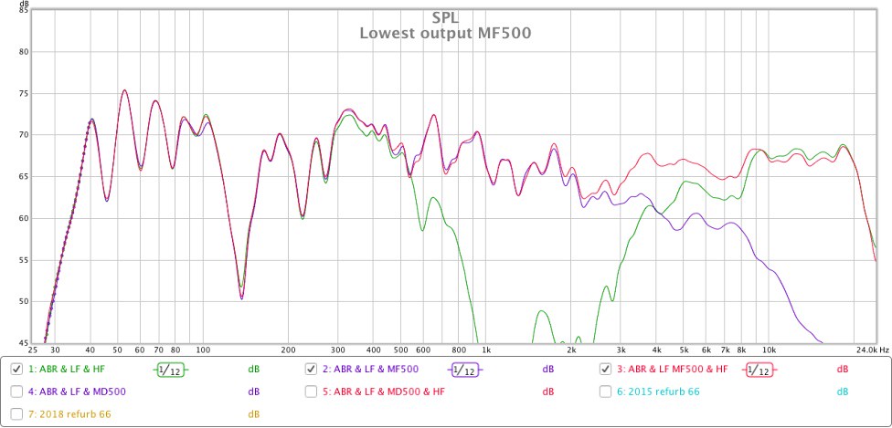
This graph compares a) the response of the 66 with the mid unit disconnected, to b) the response of the 66 with the lowest output MF500 installed and HF2000 disconnected, to c) the final response with all drivers connected:
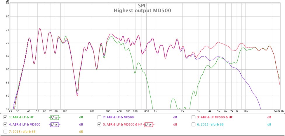
The next graph compares a) the response of the 66 with the mid unit disconnected, to b) the response of the 66 with the highest output MD500 installed and HF2000 disconnected, to c) the final response with all drivers connected:
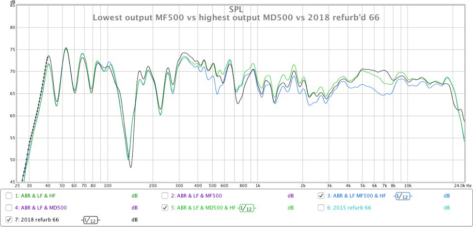
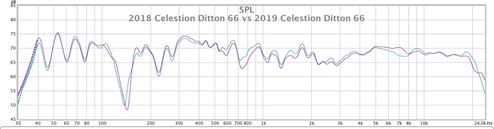
This graph compares the final response of the system with a) the lowest output MF500 installed, with b) the highest output MD500 installed, with c) the 66 loudspeaker I refurbished in 2018 that I'm using as a control reference:
I'm surprised at how much the mid unit contributes to the high frequencies. The graphs show that the HF2000 doesn't reach full output until it's beyond 10kHz. This surprised me initially, but I guess it's to be expected given the HF circuit has an 18dB high-pass filter at 5kHz. (The MF circuit is 12dB low-pass at 5kHz, isn't it?)
The lowest output MF500 causes the system's response to reduce by around 2dB between 1kHz and 4kHz, and by around 3dB from 4kHz to 8kHz, compared to the highest output MD500 I measured, and the effect of the quieter MF500 is still evident out to around 11kHz. This is not just a measurable difference, the difference in sonic character of the overall system when the quietest and loudest mid units are installed are clearly audible. The louder mid unit sounds more present, up front and forward, while the quieter unit sounds more laid back and easy going, but also a bit recessed and lacking clarity and projection.
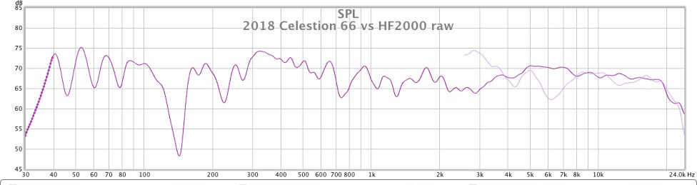
These measurements and listening impressions are of course all based on the particular HF2000 I installed in the system. It takes two to tango, so you have to consider not only the response of the mid driver but also that of the tweeter. As I explained in an earlier post, I found significant variations in frequency responses among most of the thirteen HF2000 units I measured for my previous 66 refurbishment (see here). I did however spot a 'desirable trend' among some of them, which was a flat response above 8kHz, a dip at 6kHz, and not too big a peak at 5kHz. That was the tweeter response that gave me a reasonably linear MF/HF measurement in my 2018 refurb, and is what has given me a very similar measurement in my latest refurb:
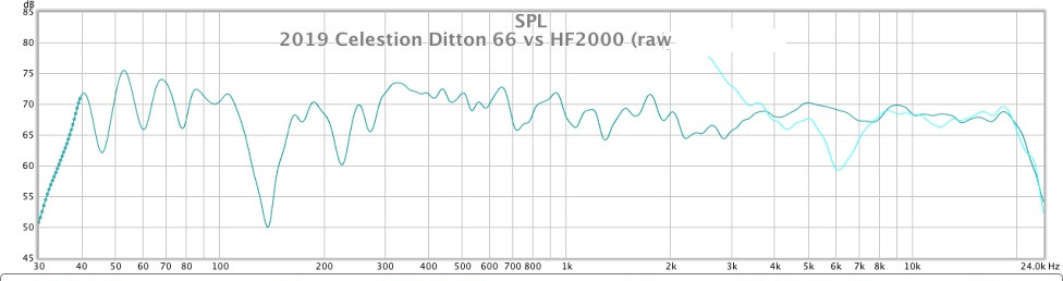
If I were however to use the MF units with lowest output, then I suspect that using HF2000 units that have higher output between 4kHz and 8kHz would combine with lower output MF500 better and raise the system output at these frequencies.
I'm opening a real can of worms here, because it was originally my intention to sell off my surplus HF2000 that didn't conform to my contrived specification, but now I'm wondering if I should hedge my bets and hold onto them in the event that I ever need to replace my MF500/MD500 units with ones that have weaker or stronger output than my incumbent ones?! Would this be safer from an electrical perspective than using DSP to boost the output between 2kHz and 8kHz? I currently use parametric EQ on my 66s to very good effect, but I use it to cut frequencies not boost them. Would boosting the output from 2kHz to 8kHz by 2dB to 3dB put the HF2000 at risk of damage, or would the MF circuit receive a greater proportion of the increase in power input required for this?
As much as I love vintage loudspeakers, the variations between identical drive units is a real headache to deal with!!! 🙁
This graph compares a) the response of the 66 with the mid unit disconnected, to b) the response of the 66 with the lowest output MF500 installed and HF2000 disconnected, to c) the final response with all drivers connected:
The next graph compares a) the response of the 66 with the mid unit disconnected, to b) the response of the 66 with the highest output MD500 installed and HF2000 disconnected, to c) the final response with all drivers connected:
This graph compares the final response of the system with a) the lowest output MF500 installed, with b) the highest output MD500 installed, with c) the 66 loudspeaker I refurbished in 2018 that I'm using as a control reference:
I'm surprised at how much the mid unit contributes to the high frequencies. The graphs show that the HF2000 doesn't reach full output until it's beyond 10kHz. This surprised me initially, but I guess it's to be expected given the HF circuit has an 18dB high-pass filter at 5kHz. (The MF circuit is 12dB low-pass at 5kHz, isn't it?)
The lowest output MF500 causes the system's response to reduce by around 2dB between 1kHz and 4kHz, and by around 3dB from 4kHz to 8kHz, compared to the highest output MD500 I measured, and the effect of the quieter MF500 is still evident out to around 11kHz. This is not just a measurable difference, the difference in sonic character of the overall system when the quietest and loudest mid units are installed are clearly audible. The louder mid unit sounds more present, up front and forward, while the quieter unit sounds more laid back and easy going, but also a bit recessed and lacking clarity and projection.
These measurements and listening impressions are of course all based on the particular HF2000 I installed in the system. It takes two to tango, so you have to consider not only the response of the mid driver but also that of the tweeter. As I explained in an earlier post, I found significant variations in frequency responses among most of the thirteen HF2000 units I measured for my previous 66 refurbishment (see here). I did however spot a 'desirable trend' among some of them, which was a flat response above 8kHz, a dip at 6kHz, and not too big a peak at 5kHz. That was the tweeter response that gave me a reasonably linear MF/HF measurement in my 2018 refurb, and is what has given me a very similar measurement in my latest refurb:
If I were however to use the MF units with lowest output, then I suspect that using HF2000 units that have higher output between 4kHz and 8kHz would combine with lower output MF500 better and raise the system output at these frequencies.
I'm opening a real can of worms here, because it was originally my intention to sell off my surplus HF2000 that didn't conform to my contrived specification, but now I'm wondering if I should hedge my bets and hold onto them in the event that I ever need to replace my MF500/MD500 units with ones that have weaker or stronger output than my incumbent ones?! Would this be safer from an electrical perspective than using DSP to boost the output between 2kHz and 8kHz? I currently use parametric EQ on my 66s to very good effect, but I use it to cut frequencies not boost them. Would boosting the output from 2kHz to 8kHz by 2dB to 3dB put the HF2000 at risk of damage, or would the MF circuit receive a greater proportion of the increase in power input required for this?
As much as I love vintage loudspeakers, the variations between identical drive units is a real headache to deal with!!! 🙁
Last edited:
Hi Alan,
have you inverted the Polarity somewhere in your Test circuit for your new Impulse Response plots ?
or are those results in the actual Polarity -{ positive and negative connections }- that your drivers are in connected to the crossovers ?
REW has a function to Invert the impulse in the Controls. Would inverting make more sense?
Hello there.
I have all the drivers from the ditton 66 and have recreated the crossovers. but without the enclosures. I am trying to recreate them.. does anybody have the baffle dimensions, ie the spacing between driver's handy ???? It would be very much appreciated as I can't find it anywhere and have been after the dimensions for some years now. many thanks..
I have all the drivers from the ditton 66 and have recreated the crossovers. but without the enclosures. I am trying to recreate them.. does anybody have the baffle dimensions, ie the spacing between driver's handy ???? It would be very much appreciated as I can't find it anywhere and have been after the dimensions for some years now. many thanks..
baffle dimensions
Some baffle dimensions for tweeter & mid were posted in this thread by sba on 10/01/2011
Some baffle dimensions for tweeter & mid were posted in this thread by sba on 10/01/2011
Thank you DennyG, It's a start in the right direction. I'm amassed that no one has posted them before..... I shell keep hunting...
Celestion 66 dimensions & driver locations
Hi Jez76,
Here are the Celestion 66 dimensions from the top in mm
Measurements were taken from a 'blackie' i.e. with a black painted front panel
top surface to bottom of lip 18
bottom of lip to tweeter flange 22
diameter of tweeter flange 100
bottom of tweeter flange to top of mid 15
diameter of mid flange 165
bottom of mid flange to top of woofer 32
diameter of woofer flange 295
bottom of woofer flange to top of ABR 35
diameter of ABR flange 302
bottom of ABR flange to top of lip 13
top of lip to bottom surface 18
Overall height 1015
Overall width 382
Overall depth not including the lip 260
Overall lip protrusion 28
Ditton 66 loudspeakers were designed according to the then current thinking: the panels were made of 3/8" plywood (I think, could check) that were expected to vibrate to some degree, so contributing to the balance in the lower registers (and "warmth").
So if you decide to adopt today's approach, in which the enclosure in intended to be inert - you would need to adjust the crossover, or accept a change in the balance and reduced output in lower registers/ resonant frequencies of the original cabinet.
I say this -after having added damping material (tar ~1/8" with metal foil backing) to the inside of my pair, and found the balance changed for the worse.
I have been informed that the original wood glue in the cabinet might have failed in some joints, which would also explain (if) the cabinet is contributing differently to the sound, than when new. I haven't attempted to dissemble the cabinet, as that would ruin the veneer which is still in good order. - my cabinets look good.
Concerning the output of the HF2000 contributing from 10kHz upward :
people might forget that the HF2000 was originally a microphone cell which was re-purposed. Celestion used the HF2000 in several designs to augment the output at upper ranges in parallel with a HF1300 tweeter which had a phase plate incorporated into the front. This phase plate extended the response until it dropped off above 10 kHz. The HF2000 was put "across" the HF1300 terminals in series with a blocking capacitor. The impedance of these HF2000 might have been 15 ohms while the HF1300 was 8 ohm, to obtain the appropriate crossover point. This combination of HF1300 and HF2000 was delightful and I made a pair of bookshelf speakers with a KEF 8 inch driver (200mm) with a crossover design from Roger Driscoll (lecturer at North London Poly and hifi writer on acoustics etc).
people might forget that the HF2000 was originally a microphone cell which was re-purposed. Celestion used the HF2000 in several designs to augment the output at upper ranges in parallel with a HF1300 tweeter which had a phase plate incorporated into the front. This phase plate extended the response until it dropped off above 10 kHz. The HF2000 was put "across" the HF1300 terminals in series with a blocking capacitor. The impedance of these HF2000 might have been 15 ohms while the HF1300 was 8 ohm, to obtain the appropriate crossover point. This combination of HF1300 and HF2000 was delightful and I made a pair of bookshelf speakers with a KEF 8 inch driver (200mm) with a crossover design from Roger Driscoll (lecturer at North London Poly and hifi writer on acoustics etc).
Ditton 66 loudspeakers were designed according to the then current thinking: the panels were made of 3/8" plywood (I think, could check) that were expected to vibrate to some degree, so contributing to the balance in the lower registers (and "warmth").
So if you decide to adopt today's approach, in which the enclosure in intended to be inert - you would need to adjust the crossover, or accept a change in the balance and reduced output in lower registers/ resonant frequencies of the original cabinet.
I say this -after having added damping material (tar ~1/8" with metal foil backing) to the inside of my pair, and found the balance changed for the worse.
I have been informed that the original wood glue in the cabinet might have failed in some joints, which would also explain (if) the cabinet is contributing differently to the sound, than when new. I haven't attempted to dissemble the cabinet, as that would ruin the veneer which is still in good order. - my cabinets look good.
When I refurbished my first pair of 66, I followed another 66 owner's refurbishment to the letter and put 2mm bitumen panels on the top and bottom cabinet walls, leaving the sides and back untouched. When I refurbished my second pair of 66, I chose not to line any of the panels with bitumen.
I prefer the tonality of the upper bass and lower mids in my first pair, my second pair by comparison sound bloated in this area and measurements confirm that my second pair have around 2dB or 3dB greater output between 300Hz-600Hz. However I don't think two small panels of 2mm bitumen can be responsible for such a difference. More likely it is caused by variations in the sensitivity of the bass and mid drivers I used in the two refurbishments, and perhaps even variations in inductor values which could alter the crossover points and slopes. Indeed, in my most recent third refurbishment, I also chose not to line any internal walls with bitumen panels, and the measured response from 300Hz-600Hz is very similar to my first refurbishment, so I don't think lining just the top and bottom walls of the 66 enclosure is enough to affect the response.
Given that the MF500/MD500 is a sealed dome unit, I assume that the internal construction of the 66 enclosure will only have an impact on the frequencies produced by the bass driver and ABR, yes? According to my measurements in post #1214, the bass driver crosses over at 540Hz and is -20dB down in output by 900Hz. Thus, in theory, it should be possible to alter the response below 900Hz by adding damping panels inside the cabinet without affecting the response above 900Hz.
I don't suppose you took any frequency measurements that show the effect of adding and removing the damping panels to your 66s? I'd be very interested to see which frequencies are most affected.
Thank You so much DennyG. thats all I need to start building a pair... very much appreciated.
Correction to my Post #1222 of 5th May
In my Post #1222 of 5th May on Page 1023 I see I have written a mistake in:
Where I stated:
" and in the case of the MDs it seems that the new adhesive hardens over time more so than the original in the MFs and thus the scratching sound that one of the early contributors to this thread found in his MDs -{ though there could be another reason for that }."
I should have stated:
and in the case of the MDs it seems that the new adhesive expands or fractures over time
... that is the word "hardens" should be "expands" , and add "or fractures"
... and I should have re-read my draft again before posting it and found that !
The expanding or fracturing could be result of excess heat if the speakers were played too loudly for too long , as the mid-domes are subject to a lot of Power dissipation as they are crossed low at around 500 Hz , and there is still some significant dome movement in the Octave below 500 Hz ... and I'll say more about that in my next Post to ToTo man.
If any of you who have MD500s with no buzzing fault , perhaps Celestion changed the adhesive again for later batches.
In my Post #1222 of 5th May on Page 1023 I see I have written a mistake in:
About your MF and MD 500 queries there and here ,
so far as I can understand from everything posted about both in this thread both are the same design , but it seems likely that Celestion upgraded either the Insulation of the voice-coil winding for the MD or upgraded the Adhesive used for connection of voice-coil to diaphram to a higher Heat tolerated type.
Either above would allow higher Power use.
Yes , as soon as one thing is changed in a design then it causes something else to change , and in the case of the MDs it seems that the new adhesive hardens over time more so than the original in the MFs and thus the scratching sound that one of the early contributors to this thread found in his MDs -{ though there could be another reason for that }.
Thus , if you have working MFs then keep them , as they may survive longer than MDs , and definitely if you do not overdrive them into too much Heat dissipation for their lower powered voice-coils.
Where I stated:
" and in the case of the MDs it seems that the new adhesive hardens over time more so than the original in the MFs and thus the scratching sound that one of the early contributors to this thread found in his MDs -{ though there could be another reason for that }."
I should have stated:
and in the case of the MDs it seems that the new adhesive expands or fractures over time
... that is the word "hardens" should be "expands" , and add "or fractures"
... and I should have re-read my draft again before posting it and found that !
The expanding or fracturing could be result of excess heat if the speakers were played too loudly for too long , as the mid-domes are subject to a lot of Power dissipation as they are crossed low at around 500 Hz , and there is still some significant dome movement in the Octave below 500 Hz ... and I'll say more about that in my next Post to ToTo man.
If any of you who have MD500s with no buzzing fault , perhaps Celestion changed the adhesive again for later batches.
Comments on Posts from #1223 to Date - first of two responses
Hello harnfield ,
it has been a long time since you last posted ... I hope your 66s are still providing some satisfaction for you. I will be very surprised if any of the cabinet panels of the 66 are 3/8" plywood , but more likely would be 5/8" ... or possibly thicker as the Top and Bottom and front baffle seem to be 3/4". Perhaps the side panels are only 1/2" , but perhaps thicker if they are rebated to allow the front baffle to be fitted into them ... which is a manufacturing technique used to increase baffle stiffness a little.
---
Jez76 ,
in addition to using the dimensions that DennyG posted , look in both the Links that ToTo Man included in his first Post on the previous Page , as there are photos of empty 66 cabinets in one of those , thus the internal layouts can be seen , and several other things of use , in particular see those tall wedge shaped pieces of Foam - those are necessary to prevent standing waves developing in the vertical Height dimension of the cabinet because any standing waves there are upper Bass frequencies and will interfere with the motion of the Woofer and cause an uneven Bass response. The original Foam type may be no longer manufactured , but for the wedges any type of Mattress foam will be sufficient , however the Height of each wedge needs to be at least one quarter of the internal height in the cabinet so as to be an effective Quarter-Wave disperser -{ though it is actually more a Half-Wave preventor in its primary application there }. You can use slightly more than one Quarter of height , but less will be not fully sufficient. My guess is those wedges are placed upside-down at the inside Top of the cabinet , and with their points wedged one each side of the back cylinder of the mid-dome enclosure for it to hold them in place. Cut their rectangular base section sufficient to cover the full Depth of the cabinet , but allowing for Foam to fit against the back panel.
For the Top , Bottom , Sides and Back panels' foam , those are required to be suitable acoustic absorptive grade of foam , and the most readily available now , and somewhat better than the original , is the Egg-crate looking profiled foam which is available in large pieces from: Amplifier valve kits, HIFI pre-amplifiers, speaker kits, AMP Parts, upgrade components | Hifi Collective
Look in "Loudspeaker Accessories" under "Acoustic Dampening". Buy the Jantzen Egg Crate Foam - 40x20 thickness profile , not the thinner 30x15 because 30x15 will not absorb the frequencies from the back of the Woofer which spread entirely within the cabinet and if no absorptive will reflect back through the woofer cone and cause colouration of the sound.
Do not use mattress foam for those parts , because mattress foam does not sufficiently absorb sound waves , and it does not absorb in a linear manner thus there will be significant colouration of the sound if mattress foam is used -{ except for the Wedges , because that is a different audio application }.
About cabinet size: If you have any doubts about Internal Dimensions of the cabinet , and/or if you want to use thicker wood for its construction . then make the Internal Volume slightly larger but not smaller , because smaller internal volume will cause a humped upper-bass response ... such as is the case with the Celestion 25 which was designed to sound LOUD , but it does not have an even linear frequency response.
Also , I recommend that you install the Crossover down behind the ABR , and not behind the Woofer , because the Magnetic Field from the woofer is strong and couples with the magnetic fields around the crossover inductors. There will be clearer sound with the crossover away from the back of the woofer , and two other contributors to this thread have found that. If you don't want the crossover behind the ABR then put it behind the mid-dome - tweeter area.
And , better sound will be achieved if you make a larger sized board for the crossover and space the Inductors further apart - see my Post #1022 on Page 103 of this Thread for how I recommend the Inductors be placed.
Also , cut the baffle height for the ABR so that inside its moveable diaphragm is not part-covered by the bottom panel foam. ABRs work best with no foam over the back of their diaphragms -{ but a little over the back of its metal frame is not a problem }. Moving the ABR slightly up towards the bottom of the Woofer will not cause any audible problems.
Finally , I strongly recommend that you do not make the Top of the cabinet with a Lip hanging over the Tweeter. That Lip causes audible problems in the Treble. I think that Celestion had it there simply for cosmetics - to look nice , and for the Grille to fit neatly under. Design a different type of Grille , and leave the front-top flat with no overhang.
---
ToTo Man ,
read in the above about placement of the crossover board. It will be worth trying that when you assemble your third pair of 66s. If you want to keep the cable connection terminals at the bottom of the back panel then get some Spacers to put behind the crossover board to hold it away from the backs of the terminals , and sufficiently for no Metal or Solder on the back of the crossover board to be able to short-circuit touch the cable terminals.
I'll post more to you , and to DennyG , in a separate post below this one.
Second post of comments
Hi DennyG ,
The Impulse Response under the first frequency response in your Post #1213 is in correct Polarity.
The Step Responses of your mid-domes in #1218 are in Inverted Polarity , but do not worry about that because those Step Responses show that both domes are in good condition , as there is a fairly smooth curve shape and no large ripples of breakup.
For Post #1219 , what Vertical Axis did you measure on ? Is it on Tweeter Axis ? or Mid-dome Axis ? or at some height in between both ? or ?
Also , that short burst of small ripples before the first spike , and there is similar in ToTo Man's Celestion plot , but not in his Tannoy plot. Do you know if those Ripples are residue of a Filter or similar within the Test Device ? or a result from the loudspeaker ? That is , has any other speaker driver you have measured with the same test equipment given that type of small-ripple initial response ?
And as it seems that you are now content with the sound from your 66s I ask: what value of Resistance did you finally decide for connection in Series with the 3.9uF cap in Parallel with the mid-domes ?
ToTo Man ,
see there is a long tiny initial ripple before the primary speaker response in your Celestion IR plot but not in your Tannoy IR plot. Do you know the reason for that difference ? ... which I ask before I start speculating as to why it may be in yours and DennyG's Celestion responses.
DennyG ,
there is a lot in what S. Linkwitz stated in that Link you posted , and it is interesting and useful , however where he states:
"A recent audiophile magazine review of a 3-way speaker, with response similar to (e) above claimed: "... The step response indicates that the tweeter and midrange unit are connected with positive acoustic polarity (the sharp up/down spike at 0 ms and the lazier triangle 0.4 ms later), while the woofer is connected with negative polarity (the broad, negative-going hump centered between 1.5 and 2.5 ms). The actual drive-unit polarity doesn't matter except when it comes to waveform preservation -- and the jury is out on that subject." "
I respond that "the jury" will be "out on that subject" for a long time until people realize that each of us hears Polarity differences differently - that is , some people's ear/brain does not allocate any significant priority to relative Polarities when the differences do not change the steady-state Frequency Response , but other people's ear/brain does detect relative differences in Polarity even when the steady-state Frequency Response is not changed. The above can easily be demonstrated by using a symmetrical 3rd Order crossover for a simple two-way loudspeaker , because with 3rd Order Butterworth the Frequency Response will sum to flat with both drivers in same polarity and when the polarity of one of the drivers is reversed - if one is listening or measuring on the Vertical Axis where there is equal signal arrival time from both drivers. But if one listens above or below the optimum Vertical Axis then the measured and heard frequency response does change with polarity change of one driver versus the other.
Currently I am listening to a dual-concentric drivers' loudspeaker with 3rd order crossover , thus no change of frequency response off-axis -{ except some highest octave of treble roll-off }- when one driver's polarity is changed relative to the other , but very audible Transient Response change to my ear/brain , but not to some other listeners.
I have always heard the difference , from many years ago before I even knew that there were crossover networks in multiway loudspeakers of otherwise similar frequency responses , and after studying different types of crossover networks I then realized why I was hearing the differences in Transient Response. I found over the years that some listeners prefer one option of polarity connection and other listeners prefer the opposite , and that some listeners seem to not hear any difference between the two options ... thus one reason why some many different loudspeakers with same measured frequency response sound different to so many listeners -{ one amongst several reasons why }.
---
ToTo Man ,
You do not need to measure Impedance to better match your drivers , as you have suitable test equipment to better match another way.
I refer you to the Impedance plots that DennyG posted in #1213 , and more-so to the substantially larger differences in Impedances between drivers that sba posted on Page 36 of this Thread in #354 , #355 , #356.
Look specifically at the differences at the lower frequency end for the mid-domes and for the tweeters ... see the Magnitude differences at the Fs for each driver , and the actual Frequency of each driver , and the bumps higher in Frequency for some of those drivers. All those anomalies in Impedance interact with the crossover network , and in particular cause the outputs of the drivers to be different to each other in those frequency regions , and that may explain the lower mids hump between 300 Hz and 600 Hz that you mentioned for one pair of 66s.
To use when measuring differences between the HF2000 tweeters , ideally obtain a 6uF or 6.2uF plastic film capacitor , but if you have a 5.6uF or 6.8uF that will suffice , but preferably not an electrolytic capacitor because it will time smear the measurements somewhat.
To use when measuring for MD500 and MF500 impedance differences , ideally obtain a 24uF or 25uF plastic film capacitor , though 27uF will suffice , and anywhere between 22uF and 33uF can be used , but again preferably not electrolytic if you want to see more accurate results.
Do NOT use 4.7uF in Parallel with 1.5uF , nor 1uF in Parallel with your 23.4uF E-caps , because both can cause pulse disturbances in the results plots.
{ Audio enthusiasts need to understand that connecting capacitors in Parallel adds to larger Capacitance for Storage of Charge , which is basically DC phenomena , but that connecting capacitors in Parallel for AC - which is what Audio frequencies are - is not simply storage of charge but is Time-Constant and Pulse relative. }
As you are assembling a third pair of 66s I recommend that you buy 6uF and 24uF or 25uF polypropylene caps , -{ and 3.9uF or 4uF polypropylene for the mids' cap in parallel with the mid-domes , and better than Alcaps for the woofer crossover }- and then you will have a different type of crossover that you can use to assess audible differences , as well as useful caps for test measurements.
All are available in the UK , but some are physically large size -{ especially the 6uF cap }- however smaller physical size of same audio quality are available from Germany and USA - if you can buy by Mail-order - and the German prices are a little lower as also is their Shipping cost to UK.
You will need some Resistors , which are available in good quality types from most of the caps' sellers , and also some Egg Crate foam to stick under that top-lip of the cabinet so that you can get non-interference tweeter measurements -{ and clearer treble sound }- , and that is available in smaller pieces from another retailer than the large pieces I posted to Jez76 about. The resistors will smooth out the bumps you have found around the crossover frequencies , and that will be different for different relative impedance drivers , but as you already know there will be measurement anomalies around crossover frequencies relative to different Vertical Axis measurement heights.
Also , for when measuring the individual drivers mounted on the 66 cabinet when you later measure them each in turn connected to the crossover network you will need Load Resistors to connect across the output sections of the crossover that are open circuit when you disconnect the not-to-be measured drivers , because if no Load connected those seemingly open-circuit sections of the crossover are not actually complete open-circuit but become additional Loads on the remaining driver connected that you attempting to measure , plus they are also then resonant almost short-circuits across you Amplifier output at certain specific frequencies , and which risks damage to the output stage of your amplifier when driving the partially un-loaded crossover. Load Resistors used for testing do not need to be high audio quality , but need only be of sufficient Power rating to not overheat. For low level testing 5 watt ceramic coated wire-wound resistors are sufficient , but I recommend 10 watt resistor in place of the woofer if you want to test mid-domes to higher voltage levels.
Also , and as you do not like Soldering , and for faster testing , you can make some Test Leads with suitable lengths of cable and Alligator/Crocodile clips attached to simply clip onto the terminals of the drivers and capacitors. Look in: Cricklewood Electronics | CCTV Online Store for their 35mm with both Red and Black insulated clips to use for Polarity identification ... 35mm is ideal size , larger is less useful.
Cricklewood also sell 25uF Ansar Supersound poly caps , but if you want smaller physical size I'll list other Sellers.
In one of your 66s photos I see the 23.4uF measured 22uF E-caps you mentioned -{ connected in problem causing Parallel with a 1uF poly cap } , but in another 66 photo I see you have what looks like three E-caps in Parallel -{ and another Parallel poly cap }- but I cannot read the uF values of those three , thus I ask you what are those ? ... because you might be able to use those with the 23.4uF E-caps to better use in the woofer circuit if you decide later to change all your crossovers to poly caps in the midrange.
I have to Log Off and leave this computer now , thus if you are interested in any of the above then please Post about it soon , and when I next get computer access time I will reply , plus comment further about the Impulse Response and/or Step Response plots.
Last edited:
Hi Alan,

REW tests on other speakers also have that increasing ripple starting at about -0.6 to -0.5 mS.
I assume the ripples before the sharp rise are intended to 'warm up' the sound card. I can't find anything in the REW documentation but for Speaker Workshop there are 'warm up' settings described as follows:
"The sound card you use may very well have startup issues when starting a record operation due to things like capacitors charging up and clocks getting to speed. As an option, Speaker Workshop lets you send a short low-level signal to the card before the actual data is sent. This seriously improves the measurement quality for a single sample and marginally improves multi-sample tests as well. The default of 100 seems to work well. A longer default would help with a card that takes a long time to get to full performance. This can be checked by doing a simple Measure Impedance of a driver with a single MLS sample with different warmup settings"
I haven't experimented with the series resistor in the 4 uF circuit. It's still 2.7R.
That is interesting and worth remembering. I understood that driver polarity orientation was determined by the crossover but it's obviously far more complicated.
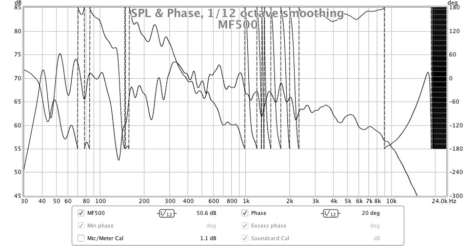
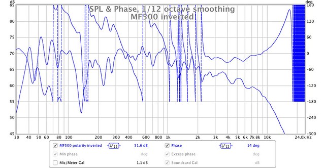
The chart below is the PTB_MF500_L Impulse response and calculated Step response using the REW software after inversion using the REW Controls. It now looks like the Response using Holmimpulse. There is no inversion option in Holmimpulse that I can see and the default setting for REW is for no inversion so why the REW measurement is inverted is a mystery. Something to check next time.The Step Responses of your mid-domes in #1218 are in Inverted Polarity , but do not worry about that because those Step Responses show that both domes are in good condition , as there is a fairly smooth curve shape and no large ripples of breakup.
For post #1219 I measured on the tweeter axis which is 920 mm above the floor level.For Post #1219 , what Vertical Axis did you measure on ? Is it on Tweeter Axis ? or Mid-dome Axis ? or at some height in between both ? or ?
Also , that short burst of small ripples before the first spike , and there is similar in ToTo Man's Celestion plot , but not in his Tannoy plot. Do you know if those Ripples are residue of a Filter or similar within the Test Device ? or a result from the loudspeaker ? That is , has any other speaker driver you have measured with the same test equipment given that type of small-ripple initial response ?
REW tests on other speakers also have that increasing ripple starting at about -0.6 to -0.5 mS.
I assume the ripples before the sharp rise are intended to 'warm up' the sound card. I can't find anything in the REW documentation but for Speaker Workshop there are 'warm up' settings described as follows:
"The sound card you use may very well have startup issues when starting a record operation due to things like capacitors charging up and clocks getting to speed. As an option, Speaker Workshop lets you send a short low-level signal to the card before the actual data is sent. This seriously improves the measurement quality for a single sample and marginally improves multi-sample tests as well. The default of 100 seems to work well. A longer default would help with a card that takes a long time to get to full performance. This can be checked by doing a simple Measure Impedance of a driver with a single MLS sample with different warmup settings"
And as it seems that you are now content with the sound from your 66s I ask: what value of Resistance did you finally decide for connection in Series with the 3.9uF cap in Parallel with the mid-domes ?
I haven't experimented with the series resistor in the 4 uF circuit. It's still 2.7R.
there is a lot in what S. Linkwitz stated in that Link you posted , and it is interesting and useful , however where he states:
"A recent audiophile magazine review of a 3-way speaker, with response similar to (e) above claimed: "... The step response indicates that the tweeter and midrange unit are connected with positive acoustic polarity (the sharp up/down spike at 0 ms and the lazier triangle 0.4 ms later), while the woofer is connected with negative polarity (the broad, negative-going hump centered between 1.5 and 2.5 ms). The actual drive-unit polarity doesn't matter except when it comes to waveform preservation -- and the jury is out on that subject." "
I respond that "the jury" will be "out on that subject" for a long time until people realize that each of us hears Polarity differences differently - that is , some people's ear/brain does not allocate any significant priority to relative Polarities when the differences do not change the steady-state Frequency Response , but other people's ear/brain does detect relative differences in Polarity even when the steady-state Frequency Response is not changed. The above can easily be demonstrated by using a symmetrical 3rd Order crossover for a simple two-way loudspeaker , because with 3rd Order Butterworth the Frequency Response will sum to flat with both drivers in same polarity and when the polarity of one of the drivers is reversed - if one is listening or measuring on the Vertical Axis where there is equal signal arrival time from both drivers. But if one listens above or below the optimum Vertical Axis then the measured and heard frequency response does change with polarity change of one driver versus the other.
Currently I am listening to a dual-concentric drivers' loudspeaker with 3rd order crossover , thus no change of frequency response off-axis -{ except some highest octave of treble roll-off }- when one driver's polarity is changed relative to the other , but very audible Transient Response change to my ear/brain , but not to some other listeners.
I have always heard the difference , from many years ago before I even knew that there were crossover networks in multiway loudspeakers of otherwise similar frequency responses , and after studying different types of crossover networks I then realized why I was hearing the differences in Transient Response. I found over the years that some listeners prefer one option of polarity connection and other listeners prefer the opposite , and that some listeners seem to not hear any difference between the two options ... thus one reason why some many different loudspeakers with same measured frequency response sound different to so many listeners -{ one amongst several reasons why }.
That is interesting and worth remembering. I understood that driver polarity orientation was determined by the crossover but it's obviously far more complicated.
Hi Alan,
Many thanks for your incredibly detailed response, frustratingly the forum did not automatically notify me of your reply this time so I have only just seen it this evening. I will give it a proper read tomorrow but sadly probably won't be able to implement any of your recommendations in my latest 66 refurbishment as it is now all but complete and going to its new owner in a couple of days (two weeks behind schedule)!
I do have one quick question in the meantime that I'm quite embarrassed to ask.... In the 66, is there only one "correct" polarity for the mid driver (relative to the woofer), and if so, what is it? Identifying the correct polarity for the tweeter is easy on the frequency response graph, but isn't quite so obvious for the mid. In fact inverting the polarity on the mid seems to give a flatter amplitude response (when measured nearfield and on-axis with the mid, at least), with less of an upper-bass / lower-midrange hump that is one of my complaints of the 66. I'm thinking that wiring the mid this way (i.e. inverted) could negate my usual need to apply EQ to knock a few dBs off this part of the frequency response. This however will mean the mid driver will be receiving more power with no EQ attenuating these frequencies. I also don't want to throw the baby out with the bathwater and introduce other problems, such as unpredictable off-axis responses etc. Did you experiment with the polarity of the mid drivers in your 66s? I'd be interested to hear your subjective conclusions?
Last edited:
Hi again Alan,
Sadly I don't know the reason for this, above my pay grade I'm afraid!
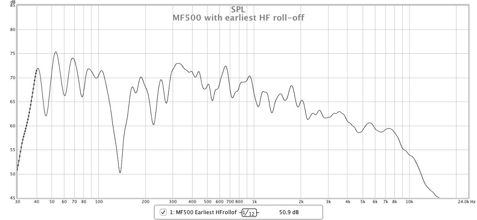
I think I discovered what you describe above when I measured all of my HF2000's in-circuit. I made all HF measurements using the same MF500 driver, because it would have been far too time consuming to measure every possible MF/HF combination. The following graph shows the in-circuit response of the MF500 I used. I chose the MF500 with the earliest HF roll–off, but there was no particular motive behind this.
The following graphs shows the complete system response with each of the thirteen HF2000 units (all measurements were taken nearfield at 1m distance and on-axis with the MF500:
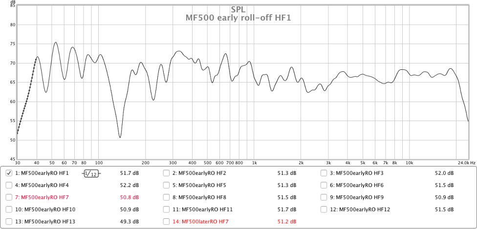

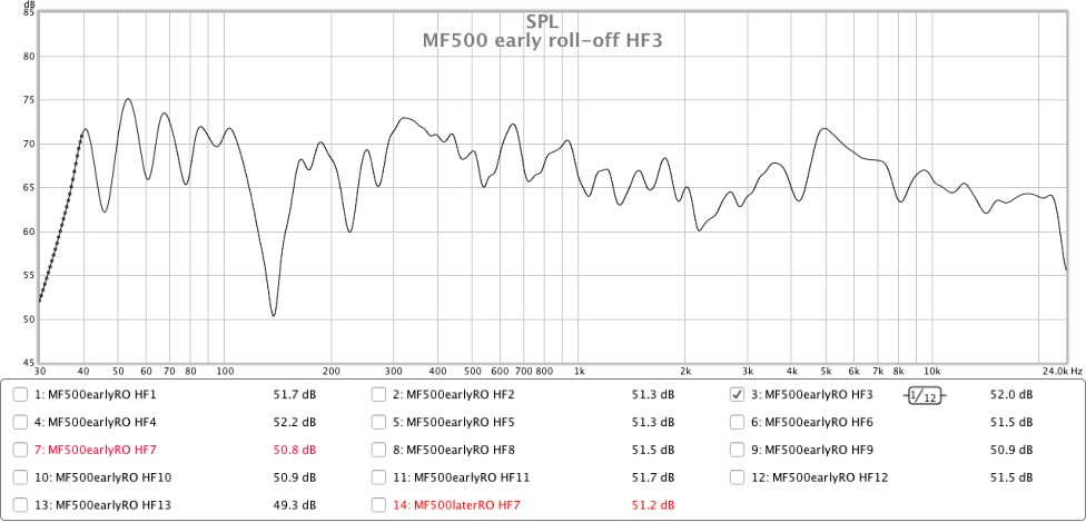
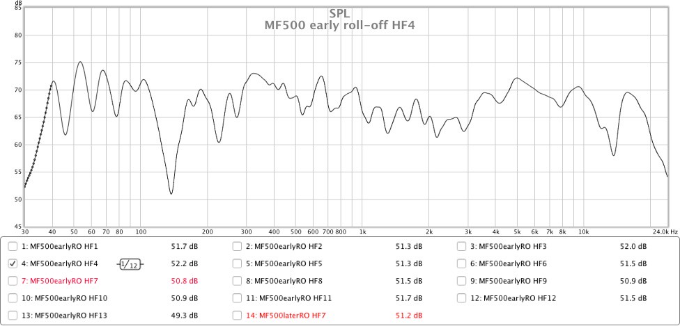
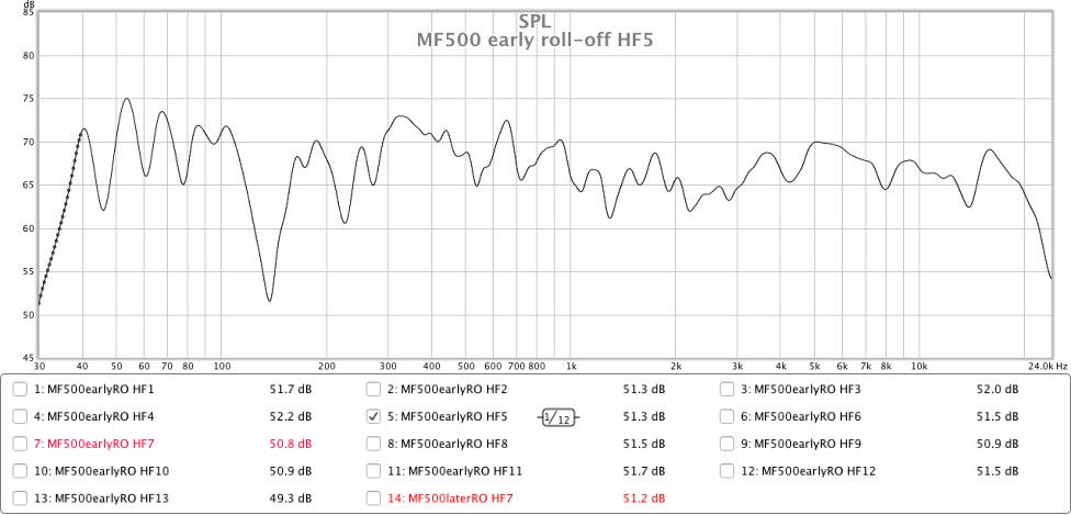

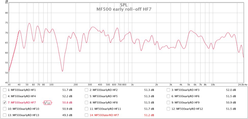
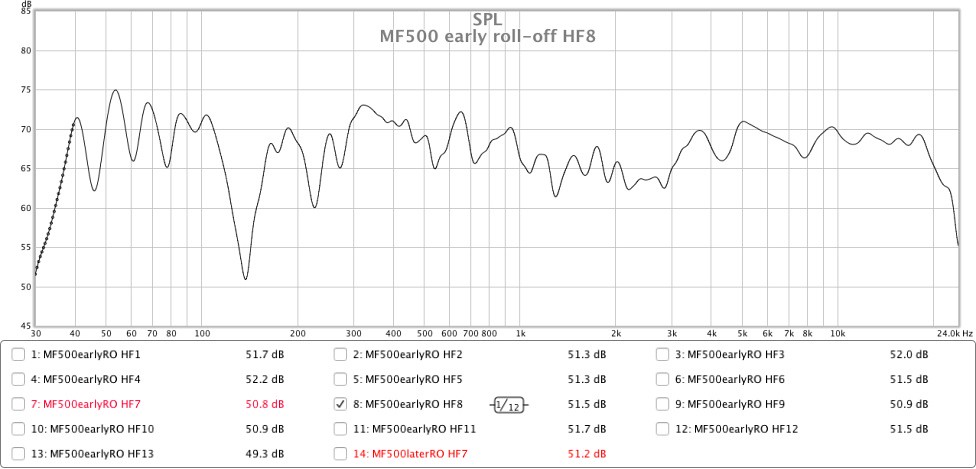
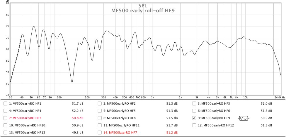
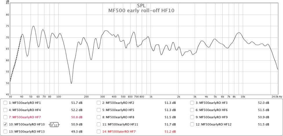
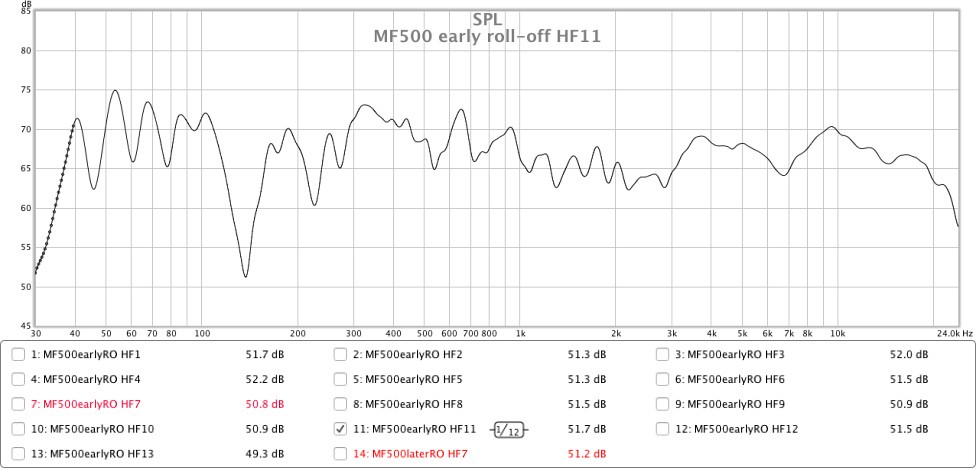
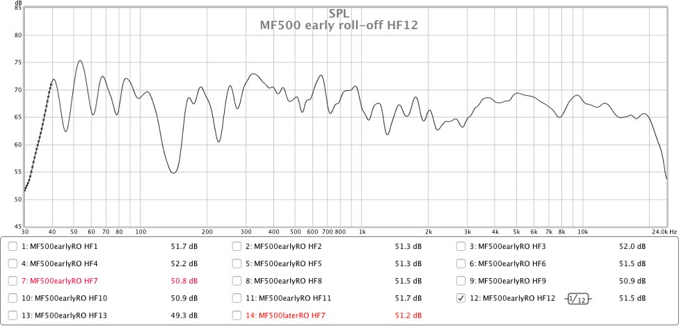
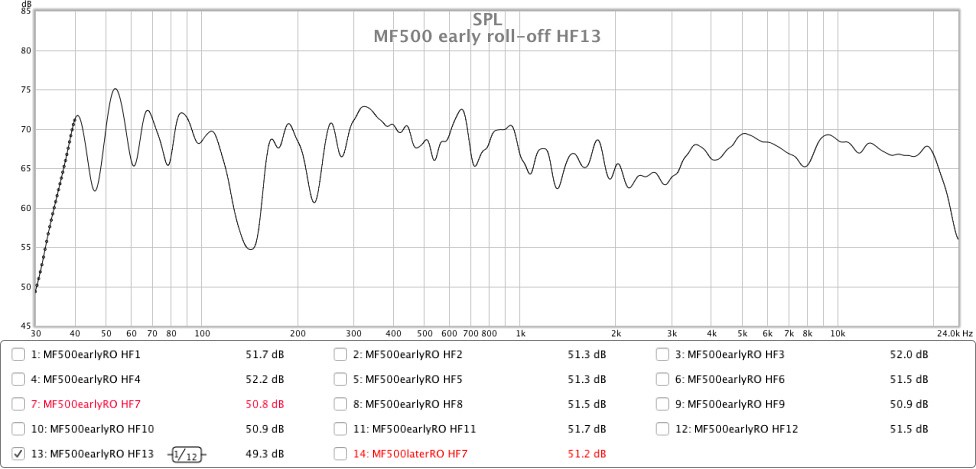
Based on the above graphs, my sample of thirteen HF2000s can be grouped as follows:
a) those that produce a smooth(ish) response through the crossover frequency (i.e. HF1 HF6, HF8, HF9, HF10, HF11, HF12, HF13).
b) those that produce an elevated/peaked response through the crossover frequency (i.e. units HF2, HF3, HF4, HF7).
c) those that display other frequency anomalies (i.e. units HF3, HF4, HF5, HF7, HF10).
The response of HF7 (highlighted in red) interested me, so I repeated its measurement with a MF500 unit that doesn’t roll-off as the MF500 I used for the above measurements:
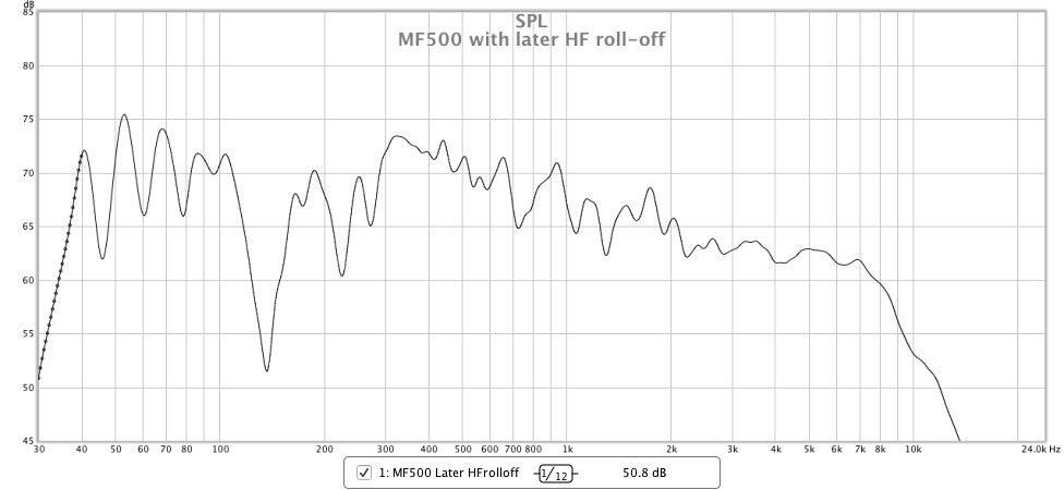
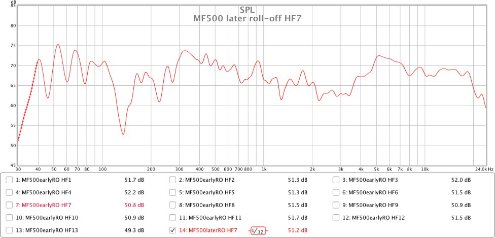
Using this mid driver causes HF7’s response to change significantly, not only increasing the level of output at these overlapping frequencies but also smoothing out the response, the latter of which I was not expecting. This demonstrates that is important to measure the candidate MF500 and HF2000 drivers together as a complete system to see how they interact with each other.
As mentioned above, all of the measurements were taken at a distance of 1 metre with the microphone on-axis with the MF500. They could therefore be completely meaningless in the context of a normal farfield listening situation where vertical height has much less impact on the frequency response around the MF/HF crossover area. I did not repeat any of the above measurements at farfield distance as it would have doubled my workload and would have also necessitated disturbing the position of my microphone which has remained perfectly static for the last 6 weeks! I do however wonder in hindsight if I’d have been better not bothering with the nearfield measurements and just done farfield ones?!
I also measured the distortion of each HF2000 when installed in the system to see if it would explain the differences in frequency response:
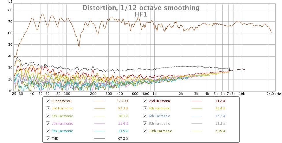
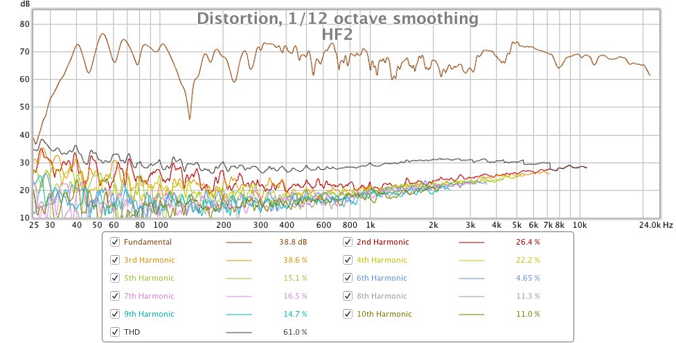
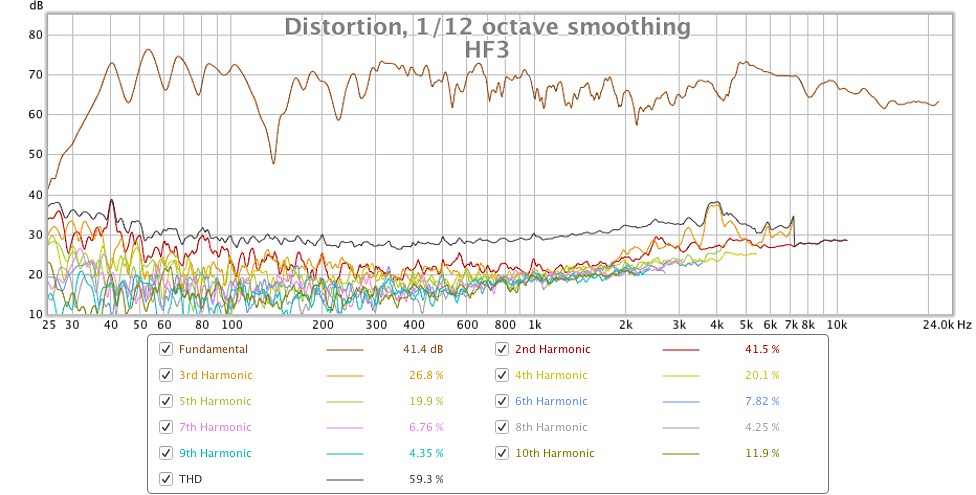
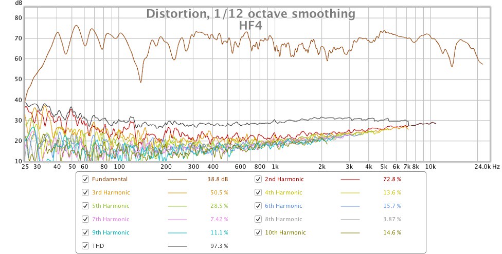
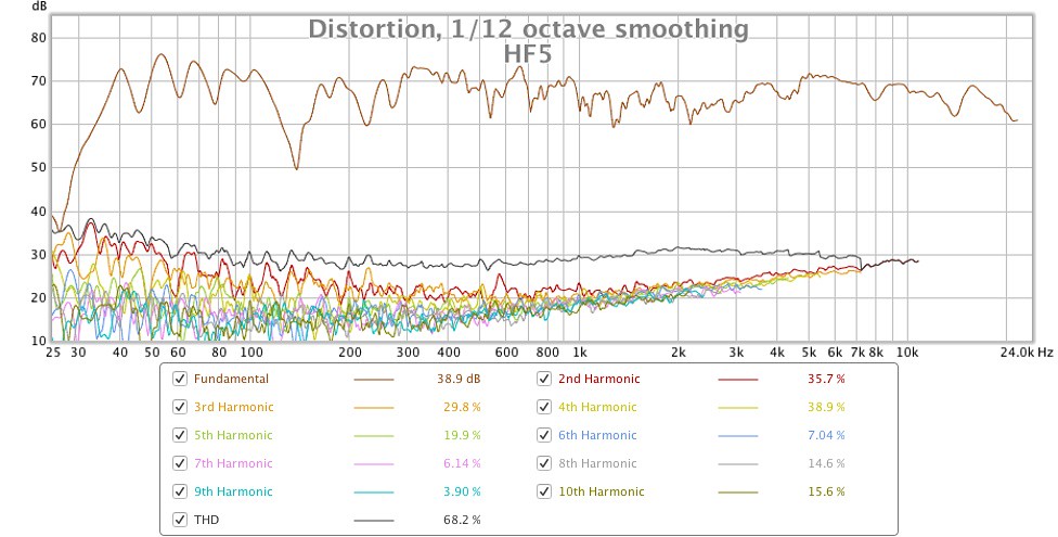
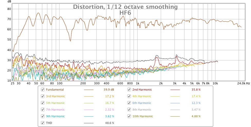
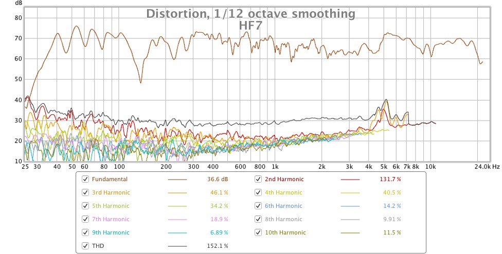
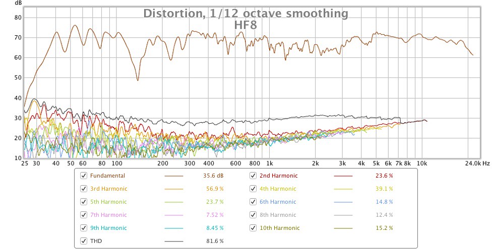


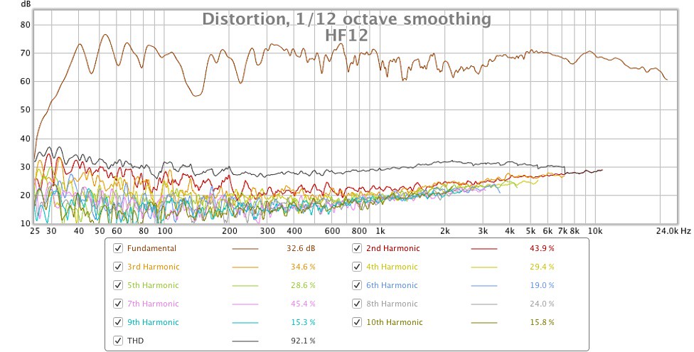
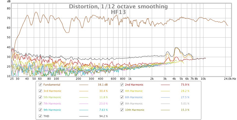
The short answer is, “no conclusive correlations can be made”. Some HF units that have ‘anomalous’ frequency responses show elevated levels of distortion, whilst others do not, and some HF units that have desirably flat frequency responses actually show elevated levels of distortion! I do not know if these levels of distortion would be audible in normal use, I certainly didn’t notice it during my brief listening of each tweeter installed in the system, then again I wasn’t listening to the speaker at head-banging SPLs!
I’m not sure I understand. Is the method of measuring you describe above different to what I have done?
Regarding the advice not to use parallel caps, is this just for the purposes of obtaining reliable measurements or are you also advising against the use of parallel caps for final installation? I have no knowledge of crossover design, nor what is considered best practice. For my previous two refurbishments I followed the advice of an AoS forum member who had done extensive experimentation on his 66s trying different cap combinations trying to walk the proverbial tight rope between improving the performance of his 66s whilst preserving the original tuning as much as possible. This led me to being recommended:
Alcap electrolytics in the LF and MF shunt position.
95% / 5% mix of Mundorf ECap and Ansar SuperSound in MF circuit.
Ansar SuperSound in the HF circuit.
I was told to use 30uf for the MF500 and 24uf for the MD500, and that when making up the value with multiples of the same cap brand it was better to use as close as values as possible to each other, e.g. if 26uf is not available in a single cap then it is better to make it up from 10uf+8uf+8uf than from 20uf + 6uf.
I recall trying egg foam under the top lip of the cabinet for my first 66 refurb a few years ago but didn’t measure much if any difference in the HF response. I’ll try again though.
I do actually have load resistors (4.7 ohms and 6.7 ohms IIRC) but have been too lazy to use them! I was aware that disconnected loads place additional strain on the amp but figured it would be safe enough for 6 second frequency sweeps at 70dB. I was not however aware that the unconnected load would would affect the loading and thus response of the connected loads. In fact I showed the 66 crossover schematic to an EE and he was fairly sure the circuits were independent of each other. Again this is something way beyond my current level of knowledge.
Great minds think alike! I bought some crocodile clip test leads a fortnight ago and they have indeed been an invaluable means of efficiently swapping out different MF500 and HF2000 units!
I think I might have answered this above, but for my 2015 refurb with MF500 drivers I aimed for 30uf made up from Mundorf E-Caps 10uf+8.2uf+8.2uf and Ansar SuperSound poly 1.5uf (this adds up to 27.9uf on paper but when I measured them the total was 30.6uf). For my 2018 refurb with MD500 drivers I aimed for 24uf made up from Mundorf E-Cap 22uf and Ansar SuperSound poly 1uf (this adds up to 23uf on paper but when I measured them the total was 24.6uf).
Finally, just to confirm, I am not recapping the crossovers on my latest 66 refurbishment. Too much work and perhaps even unnecessary because the low- and high-pass crossover slopes measure identically for both enclosures, as does the overall frequency response (I transplanted the drivers from one enclosure to the other to confirm this). I'm sure improvements can be had, but in side-by-side listening tests with my re-capped 66s, this latest pair doesn't sound audibly different or inferior to my ears. In fact it almost makes me wonder why I bothered re-capping my other pairs!...
see there is a long tiny initial ripple before the primary speaker response in your Celestion IR plot but not in your Tannoy IR plot. Do you know the reason for that difference ? ... which I ask before I start speculating as to why it may be in yours and DennyG's Celestion responses.
Sadly I don't know the reason for this, above my pay grade I'm afraid!
I refer you to the Impedance plots that DennyG posted in #1213 , and more-so to the substantially larger differences in Impedances between drivers that sba posted on Page 36 of this Thread in #354 , #355 , #356.
Look specifically at the differences at the lower frequency end for the mid-domes and for the tweeters ... see the Magnitude differences at the Fs for each driver , and the actual Frequency of each driver , and the bumps higher in Frequency for some of those drivers. All those anomalies in Impedance interact with the crossover network , and in particular cause the outputs of the drivers to be different to each other in those frequency regions , and that may explain the lower mids hump between 300 Hz and 600 Hz that you mentioned for one pair of 66s.
I think I discovered what you describe above when I measured all of my HF2000's in-circuit. I made all HF measurements using the same MF500 driver, because it would have been far too time consuming to measure every possible MF/HF combination. The following graph shows the in-circuit response of the MF500 I used. I chose the MF500 with the earliest HF roll–off, but there was no particular motive behind this.
The following graphs shows the complete system response with each of the thirteen HF2000 units (all measurements were taken nearfield at 1m distance and on-axis with the MF500:
Based on the above graphs, my sample of thirteen HF2000s can be grouped as follows:
a) those that produce a smooth(ish) response through the crossover frequency (i.e. HF1 HF6, HF8, HF9, HF10, HF11, HF12, HF13).
b) those that produce an elevated/peaked response through the crossover frequency (i.e. units HF2, HF3, HF4, HF7).
c) those that display other frequency anomalies (i.e. units HF3, HF4, HF5, HF7, HF10).
The response of HF7 (highlighted in red) interested me, so I repeated its measurement with a MF500 unit that doesn’t roll-off as the MF500 I used for the above measurements:
Using this mid driver causes HF7’s response to change significantly, not only increasing the level of output at these overlapping frequencies but also smoothing out the response, the latter of which I was not expecting. This demonstrates that is important to measure the candidate MF500 and HF2000 drivers together as a complete system to see how they interact with each other.
As mentioned above, all of the measurements were taken at a distance of 1 metre with the microphone on-axis with the MF500. They could therefore be completely meaningless in the context of a normal farfield listening situation where vertical height has much less impact on the frequency response around the MF/HF crossover area. I did not repeat any of the above measurements at farfield distance as it would have doubled my workload and would have also necessitated disturbing the position of my microphone which has remained perfectly static for the last 6 weeks! I do however wonder in hindsight if I’d have been better not bothering with the nearfield measurements and just done farfield ones?!
I also measured the distortion of each HF2000 when installed in the system to see if it would explain the differences in frequency response:
The short answer is, “no conclusive correlations can be made”. Some HF units that have ‘anomalous’ frequency responses show elevated levels of distortion, whilst others do not, and some HF units that have desirably flat frequency responses actually show elevated levels of distortion! I do not know if these levels of distortion would be audible in normal use, I certainly didn’t notice it during my brief listening of each tweeter installed in the system, then again I wasn’t listening to the speaker at head-banging SPLs!
To use when measuring differences between the HF2000 tweeters , ideally obtain a 6uF or 6.2uF plastic film capacitor , but if you have a 5.6uF or 6.8uF that will suffice , but preferably not an electrolytic capacitor because it will time smear the measurements somewhat.
To use when measuring for MD500 and MF500 impedance differences , ideally obtain a 24uF or 25uF plastic film capacitor , though 27uF will suffice , and anywhere between 22uF and 33uF can be used , but again preferably not electrolytic if you want to see more accurate results.
Do NOT use 4.7uF in Parallel with 1.5uF , nor 1uF in Parallel with your 23.4uF E-caps , because both can cause pulse disturbances in the results plots.
{ Audio enthusiasts need to understand that connecting capacitors in Parallel adds to larger Capacitance for Storage of Charge , which is basically DC phenomena , but that connecting capacitors in Parallel for AC - which is what Audio frequencies are - is not simply storage of charge but is Time-Constant and Pulse relative. }
As you are assembling a third pair of 66s I recommend that you buy 6uF and 24uF or 25uF polypropylene caps , -{ and 3.9uF or 4uF polypropylene for the mids' cap in parallel with the mid-domes , and better than Alcaps for the woofer crossover }- and then you will have a different type of crossover that you can use to assess audible differences , as well as useful caps for test measurements.
I’m not sure I understand. Is the method of measuring you describe above different to what I have done?
Regarding the advice not to use parallel caps, is this just for the purposes of obtaining reliable measurements or are you also advising against the use of parallel caps for final installation? I have no knowledge of crossover design, nor what is considered best practice. For my previous two refurbishments I followed the advice of an AoS forum member who had done extensive experimentation on his 66s trying different cap combinations trying to walk the proverbial tight rope between improving the performance of his 66s whilst preserving the original tuning as much as possible. This led me to being recommended:
Alcap electrolytics in the LF and MF shunt position.
95% / 5% mix of Mundorf ECap and Ansar SuperSound in MF circuit.
Ansar SuperSound in the HF circuit.
I was told to use 30uf for the MF500 and 24uf for the MD500, and that when making up the value with multiples of the same cap brand it was better to use as close as values as possible to each other, e.g. if 26uf is not available in a single cap then it is better to make it up from 10uf+8uf+8uf than from 20uf + 6uf.
You will need some Resistors , which are available in good quality types from most of the caps' sellers , and also some Egg Crate foam to stick under that top-lip of the cabinet so that you can get non-interference tweeter measurements -{ and clearer treble sound }- , and that is available in smaller pieces from another retailer than the large pieces I posted to Jez76 about. The resistors will smooth out the bumps you have found around the crossover frequencies , and that will be different for different relative impedance drivers , but as you already know there will be measurement anomalies around crossover frequencies relative to different Vertical Axis measurement heights.
I recall trying egg foam under the top lip of the cabinet for my first 66 refurb a few years ago but didn’t measure much if any difference in the HF response. I’ll try again though.
Also, for when measuring the individual drivers mounted on the 66 cabinet when you later measure them each in turn connected to the crossover network you will need Load Resistors to connect across the output sections of the crossover that are open circuit when you disconnect the not-to-be measured drivers , because if no Load connected those seemingly open-circuit sections of the crossover are not actually complete open-circuit but become additional Loads on the remaining driver connected that you attempting to measure , plus they are also then resonant almost short-circuits across you Amplifier output at certain specific frequencies , and which risks damage to the output stage of your amplifier when driving the partially un-loaded crossover. Load Resistors used for testing do not need to be high audio quality , but need only be of sufficient Power rating to not overheat. For low level testing 5 watt ceramic coated wire-wound resistors are sufficient , but I recommend 10 watt resistor in place of the woofer if you want to test mid-domes to higher voltage levels.
I do actually have load resistors (4.7 ohms and 6.7 ohms IIRC) but have been too lazy to use them! I was aware that disconnected loads place additional strain on the amp but figured it would be safe enough for 6 second frequency sweeps at 70dB. I was not however aware that the unconnected load would would affect the loading and thus response of the connected loads. In fact I showed the 66 crossover schematic to an EE and he was fairly sure the circuits were independent of each other. Again this is something way beyond my current level of knowledge.
Also , and as you do not like Soldering , and for faster testing , you can make some Test Leads with suitable lengths of cable and Alligator/Crocodile clips attached to simply clip onto the terminals of the drivers and capacitors. Look in: Cricklewood Electronics | CCTV Online Store for their 35mm with both Red and Black insulated clips to use for Polarity identification ... 35mm is ideal size , larger is less useful.
Great minds think alike! I bought some crocodile clip test leads a fortnight ago and they have indeed been an invaluable means of efficiently swapping out different MF500 and HF2000 units!
Cricklewood also sell 25uF Ansar Supersound poly caps , but if you want smaller physical size I'll list other Sellers.
In one of your 66s photos I see the 23.4uF measured 22uF E-caps you mentioned -{ connected in problem causing Parallel with a 1uF poly cap } , but in another 66 photo I see you have what looks like three E-caps in Parallel -{ and another Parallel poly cap }- but I cannot read the uF values of those three , thus I ask you what are those ? ... because you might be able to use those with the 23.4uF E-caps to better use in the woofer circuit if you decide later to change all your crossovers to poly caps in the midrange.
I think I might have answered this above, but for my 2015 refurb with MF500 drivers I aimed for 30uf made up from Mundorf E-Caps 10uf+8.2uf+8.2uf and Ansar SuperSound poly 1.5uf (this adds up to 27.9uf on paper but when I measured them the total was 30.6uf). For my 2018 refurb with MD500 drivers I aimed for 24uf made up from Mundorf E-Cap 22uf and Ansar SuperSound poly 1uf (this adds up to 23uf on paper but when I measured them the total was 24.6uf).
Finally, just to confirm, I am not recapping the crossovers on my latest 66 refurbishment. Too much work and perhaps even unnecessary because the low- and high-pass crossover slopes measure identically for both enclosures, as does the overall frequency response (I transplanted the drivers from one enclosure to the other to confirm this). I'm sure improvements can be had, but in side-by-side listening tests with my re-capped 66s, this latest pair doesn't sound audibly different or inferior to my ears. In fact it almost makes me wonder why I bothered re-capping my other pairs!...
Last edited:
- Home
- Loudspeakers
- Multi-Way
- Celestion 66 needs mid-range