Interim reply - for about HF2000s pair matching
Hi DennyG and ToTo Man ,
I have very little time available today , thus this post will not respond to everything.
DennyG - I will return to your Post next time ,
however thankyou about the Test Equipment warm-up pulse matter as that makes sense.
ToTo Man - first refer to what DennyG stated about those early Ripples ,
and later I'll return to your IR plots.
For now , as you are very soon to sell your Third Pair of 66s , I have examined closely all the Plots of your HF2000s - that is Frequency Response and Distortion separately.
Given how the Human Ear/Brain works , the closest to Pairs for HF2000s are as follows:
HF1 + HF9 and HF2 + HF8 - are not identical pairs but are useable as pairs.
Did you decide either of those as a Pair ?
I advise you to keep all Four of those tweeters.
HF6 + HF13 are close enough , but as both have Distortion Peaks at two different frequencies they may not sound sufficiently similar - you will have to decide that by listening.
Also , keep HF12 as a possible substitute for either of 6 or 13.
HF10 + HF11 are suitable as a Pair for a less critical listener , and are pair-like because of their similarity in around the 7kHz area
-{ note how I have matched 1 + 9 ; 2 + 8 ; 6 + 13 in the differences between 7kHz and 8kHz region which is an ear/brain critical region for Stereo Imaging }.
You could sell those as the pair in your ready-to-sell 66s ,
OR ,
sell HF4 + HF5 which are less a Pair , but some listeners are not critical listeners and will not notice the lesser matching ,
and those two are towards a Pair despite the Notch at around 13kHz , and note the similar recovery at around 15kHz.
HF4 does have a fault at 13kHz , so listen before you pair it with 5 , but for older Male listeners many have significant loss of high frequency hearing above 8kHz ,
and the 3kHz to 8kHz region of both those HFs are close enough for those loss of highest treble octave listeners.
HF3 superficially resembles HF2 , but it will not be a match for listeners who still have good hearing in the highest Treble octave.
HF3 is an odd-one-out.
HF7 , as you have identified , is also an odd-one-out , and is likely faulty around 5kHz and around 9kHz-10kHz , however your experiment with it shows something to keep in mind.
My guess is that you will have kept the two closest to pairs of your mid-domes based on your other forum posted plots.
If you want to consider closer mid-domes matching before you sell the third pair , then Post their Distortion plots here and I'll state more about those.
When I have sufficient Time available I'll explain more about the critical-frequency areas for human ear/brain.
As you have used the same one sample mid-dome to do tweeter matching , and all though the same sample crossover network , you have achieved fairly good information in the 1.6kHz to 5kHz Impedance region of all the HF2000s.
I see your mid-dome has a small peak near 1.6kHz , and that will be the predominant peak in the combined HF + MF plots , but the small differences in peaks heights at 1.6kHz are result of the somewhat different magnitudes of the fundamental resonant frequency Impedance peak of HF2000 which is interacting with the crossover differently for some of the tweeters.
The 5kHz area differences are partly result of different Impedance Magnitudes of tweeters around 5kHz , and partly the sample differences in their domes and dome attachings -{ and similar is elsewhere between 4kHz to almost 20kHz }.
If I understand correctly you are selling the third pair of 66s with their original crossover capacitors still in ? ...
if those work , and no unpleasant noises from the mid-domes on volume peaks , then OK ,
but be wary that if the 24uF or 30uF series cap to the mid-dome is towards failing then the mid-domes will be excursion damaged as significant quantities of lower frequencies will get through to them.
Those 22uF Mundorf E-caps which measure 23.4uF are sufficient for 24uF there ... if you are selling with those , or sell with E-caps 8uF + 8uF + 10uF in Parallel ...
the 1uF poly cap is not necessary , and it causes a Transient Pulse error , but some listeners like that sound.
Some people do misunderstand Parallel Section crossovers' filter sections to be "independant of each other" , but they are not ,
and particularly not when one of two of them has no Load connected whilst one or two other sections are loaded and passing Signal.
Parallel Section crossovers have less inter-dependant filter sections than Series Section crossovers , but not completely independant.
In the original 66 crossovers the Woofer and Mid-domes are connected in the Same Polarity , and the Tweeter is connected in the Reverse Polarity.
You can connect the mid-domes in whichever polarity you prefer for listening versus the woofer polarity ,
but when you change the mid-dome polarity you may have to change the tweeter polarity also for balanced sound through the crossover region
-{ which is at least one Octave on each side of the actual crossover frequency - that is two Octaves in total }.
But , when you change Polarity of Tweeter with respect to whichever Polarity the mid-dome is in the Vertical Off-Axis Nodes and Peaks swap around ,
and as result whichever polarity combination that causes a Peak to be directed upwards will cause worse audible problems from reflections from that top-lip of the enclosure.
For now try rolling up some Wool socks -{ real Wool for better sound absorption , not Polyester or Nylon }- and use double sided tape to hold them under that top-lip.
Cover fully the under down-face and over at least 8 inches of length , and to 10 inches may be better.
Cover Vertically down to the top of the tweeter flange , and better will be to cover the in-top screw-head attachment piece but no further down.
I'll post more about that later if you are interested , and there are smaller pieces of egg-crate foam available for lower prices elsewhere than the large ones I recommended to Jez76.
Egg-crate foam should be placed with its heights differences pointing down , and the top screw head attachment piece in the tweeter flange covered by one foam peak ,
with the peak against the cabinet surface - not suspended out from the cabinet face with a hollow behind it.
Last edited:
Hi Alan,
I really appreciate you replying at such short notice, - it must have taken you a long time to digest all the data I uploaded. I’m very short of time today but I will try to reply to all of your suggestions as best I can:
This is really impressive analyses, especially considering you did not have the facility to overlay graphs to see how closely the traces aligned! I had matched pairs to keep based on frequency response, without considering distortion, but I will factor the distortion into my listening tests and thus final decisions.
Despite being unable to hear tones above 13kHz, my own hearing is very acute and sensitive to channel imbalances, even on frequencies beyond 13kHz strangely enough! I have therefore selected units to keep which have closely aligned responses throughout as much of the spectrum as possible.
My gold-standard pairing is HF9 + HF11, as these have the closest frequency responses and minimal distortion. I have several other combinations identified from the units I have chosen to keep for my own use, so I’m pretty confident I have most bases covered should I need to use MF500 units with earlier or later roll-offs at the top end of their operating range.
I have inspected the distortion plots for all of the MF500s I have measured and the good news is that, unlike some HF2000s, they are all ruler flat with no elevated areas.
This info is really useful, thanks.
Yes, that is correct. They are sounding remarkably good in fact! Perhaps the red Pye caps aren’t as prone to drift as the Elcaps? (These crossovers have 30uf made up from 24uf Pye and 6uf Elcap).
Is it possible to describe what this transient pulse error sounds like?
This is good to know, thanks.
I’ll be sure to try this!
I really appreciate you replying at such short notice, - it must have taken you a long time to digest all the data I uploaded. I’m very short of time today but I will try to reply to all of your suggestions as best I can:
For now , as you are very soon to sell your Third Pair of 66s , I have examined closely all the Plots of your HF2000s - that is Frequency Response and Distortion separately.
Given how the Human Ear/Brain works , the closest to Pairs for HF2000s are as follows:
HF1 + HF9 and HF2 + HF8 - are not identical pairs but are useable as pairs.
Did you decide either of those as a Pair ?
I advise you to keep all Four of those tweeters.
HF6 + HF13 are close enough , but as both have Distortion Peaks at two different frequencies they may not sound sufficiently similar - you will have to decide that by listening.
Also , keep HF12 as a possible substitute for either of 6 or 13.
HF10 + HF11 are suitable as a Pair for a less critical listener , and are pair-like because of their similarity in around the 7kHz area
-{ note how I have matched 1 + 9 ; 2 + 8 ; 6 + 13 in the differences between 7kHz and 8kHz region which is an ear/brain critical region for Stereo Imaging }.
You could sell those as the pair in your ready-to-sell 66s ,
OR ,
sell HF4 + HF5 which are less a Pair , but some listeners are not critical listeners and will not notice the lesser matching ,
and those two are towards a Pair despite the Notch at around 13kHz , and note the similar recovery at around 15kHz.
HF4 does have a fault at 13kHz , so listen before you pair it with 5 , but for older Male listeners many have significant loss of high frequency hearing above 8kHz ,
and the 3kHz to 8kHz region of both those HFs are close enough for those loss of highest treble octave listeners.
HF3 superficially resembles HF2 , but it will not be a match for listeners who still have good hearing in the highest Treble octave.
HF3 is an odd-one-out.
HF7 , as you have identified , is also an odd-one-out , and is likely faulty around 5kHz and around 9kHz-10kHz , however your experiment with it shows something to keep in mind.
This is really impressive analyses, especially considering you did not have the facility to overlay graphs to see how closely the traces aligned! I had matched pairs to keep based on frequency response, without considering distortion, but I will factor the distortion into my listening tests and thus final decisions.
Despite being unable to hear tones above 13kHz, my own hearing is very acute and sensitive to channel imbalances, even on frequencies beyond 13kHz strangely enough! I have therefore selected units to keep which have closely aligned responses throughout as much of the spectrum as possible.
My gold-standard pairing is HF9 + HF11, as these have the closest frequency responses and minimal distortion. I have several other combinations identified from the units I have chosen to keep for my own use, so I’m pretty confident I have most bases covered should I need to use MF500 units with earlier or later roll-offs at the top end of their operating range.
My guess is that you will have kept the two closest to pairs of your mid-domes based on your other forum posted plots.
If you want to consider closer mid-domes matching before you sell the third pair , then Post their Distortion plots here and I'll state more about those.
I have inspected the distortion plots for all of the MF500s I have measured and the good news is that, unlike some HF2000s, they are all ruler flat with no elevated areas.
When I have sufficient Time available I'll explain more about the critical-frequency areas for human ear/brain.
As you have used the same one sample mid-dome to do tweeter matching , and all though the same sample crossover network , you have achieved fairly good information in the 1.6kHz to 5kHz Impedance region of all the HF2000s.
I see your mid-dome has a small peak near 1.6kHz , and that will be the predominant peak in the combined HF + MF plots , but the small differences in peaks heights at 1.6kHz are result of the somewhat different magnitudes of the fundamental resonant frequency Impedance peak of HF2000 which is interacting with the crossover differently for some of the tweeters.
The 5kHz area differences are partly result of different Impedance Magnitudes of tweeters around 5kHz , and partly the sample differences in their domes and dome attachings -{ and similar is elsewhere between 4kHz to almost 20kHz }.
This info is really useful, thanks.
If I understand correctly you are selling the third pair of 66s with their original crossover capacitors still in ? ...
if those work , and no unpleasant noises from the mid-domes on volume peaks , then OK ,
but be wary that if the 24uF or 30uF series cap to the mid-dome is towards failing then the mid-domes will be excursion damaged as significant quantities of lower frequencies will get through to them.
Yes, that is correct. They are sounding remarkably good in fact! Perhaps the red Pye caps aren’t as prone to drift as the Elcaps? (These crossovers have 30uf made up from 24uf Pye and 6uf Elcap).
the 1uF poly cap is not necessary , and it causes a Transient Pulse error , but some listeners like that sound.
Is it possible to describe what this transient pulse error sounds like?
Some people do misunderstand Parallel Section crossovers' filter sections to be "independant of each other" , but they are not ,
and particularly not when one of two of them has no Load connected whilst one or two other sections are loaded and passing Signal.
Parallel Section crossovers have less inter-dependant filter sections than Series Section crossovers , but not completely independant.
In the original 66 crossovers the Woofer and Mid-domes are connected in the Same Polarity , and the Tweeter is connected in the Reverse Polarity.
You can connect the mid-domes in whichever polarity you prefer for listening versus the woofer polarity ,
but when you change the mid-dome polarity you may have to change the tweeter polarity also for balanced sound through the crossover region
-{ which is at least one Octave on each side of the actual crossover frequency - that is two Octaves in total }.
But , when you change Polarity of Tweeter with respect to whichever Polarity the mid-dome is in the Vertical Off-Axis Nodes and Peaks swap around ,
and as result whichever polarity combination that causes a Peak to be directed upwards will cause worse audible problems from reflections from that top-lip of the enclosure.
This is good to know, thanks.
For now try rolling up some Wool socks -{ real Wool for better sound absorption , not Polyester or Nylon }- and use double sided tape to hold them under that top-lip.
Cover fully the under down-face and over at least 8 inches of length , and to 10 inches may be better.
Cover Vertically down to the top of the tweeter flange , and better will be to cover the in-top screw-head attachment piece but no further down.
I'll post more about that later if you are interested , and there are smaller pieces of egg-crate foam available for lower prices elsewhere than the large ones I recommended to Jez76.
Egg-crate foam should be placed with its heights differences pointing down , and the top screw head attachment piece in the tweeter flange covered by one foam peak ,
with the peak against the cabinet surface - not suspended out from the cabinet face with a hollow behind it.
I’ll be sure to try this!
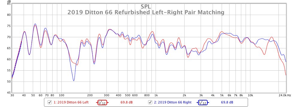
My latest refurbished 66s are now with their new owner who will hopefully be delighted with his purchase given the amount of work I put in to them, particularly with regards to pair-matching the drivers!
The final compliment includes tweeters HF4 and HF7 which, despite measuring as somewhat of oddities with the first MF500 unit I picked, actually integrate very well with the final MF500s I installed and, aside from a divergence at 14kHz which will be inaudible to a lot of listeners, they track about 1dB across most of there operating range and, when played as a stereo pair, sound pretty much indistinguishable.
Likewise the mid and lower frequencies are also very well matched to around 1dB. I'm not quite sure of the reason for the difference in amplitude of the floor bounce null at 135Hz. One enclosure had a thicker than normal section of foam damping behind the bass driver (50mm instead of 40mm) so perhaps that's the cause?
I’ve learned more during this refurbishment than my previous two, having finally taken the opportunity to measure all of my spare MF500/MD500 and HF2000 units as part of the complete 66 system. Most surprising was the extent to which the HF2000 interacts with the upper (i.e. >1.5kHz) response of the MF500/MD500, and likewise the extent to which the MF500/MD500 interacts with the lower (i.e. <10kHz) response of the HF2000. It has now become obvious to me that pair-matching by only considering the driver’s responses in isolation does not guarantee a good result.
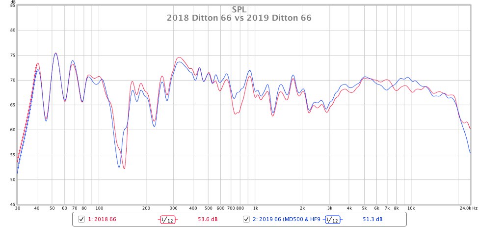
During my testing, I tried four T1600 bass drivers, six MF500 units, one MD500 unit, and thirteen HF2000 units. I noticed that regardless of the T1600 and MF500 combination used, this pair of 66s sounded consistently less coloured through the lower midrange and upper bass frequencies than my 2018 refurbished 66s. I’m curious as to why this is? The 2018 66s have measurably more lower midrange and bass output than my latest refurbishment, but we’re only talking about a difference of between 1dB and 2dB at most, and I wouldn’t have thought this would have much of an audible impact on the perceived clarity and colouration of the presentation.
If I apply a low-shelf filter EQ to my 2018 66s to reduce output by -2dB below 500Hz, their overall presentation does become clearer and less wooly and bloated and they sound much more like the 2019 66s, however they still don’t seem to have as much openness and dynamics. Do you think this could be due to my choice of capacitors? I really don’t want to go down the rabbit hole of “re-replacing” all of the caps, but is it wishful thinking that simply removing the parallel 1uf poly in the MF circuit will bring an improvement in openness, dynamics and transparency?
Interestingly, during my final stages of testing, I stumbled upon one particular driver combination that produced the best (i.e. clearest, smoothest, most transparent and dynamic) sound I have ever heard from a 66. I literally spent the entire night listening to it utterly captivated! This was achieved by pairing my only spare working MD500 driver with HF9. This MD500 in particular has approximately +2dB stronger output from 1kHz to 7kHz than any other MF500 or MD500 I have recently measured and, as you can see in the following graph, it integrates with HF9 superbly well. Again, there isn’t a great deal of measurable difference between it and my 2018 66, yet the difference is clearly audible to my ears.
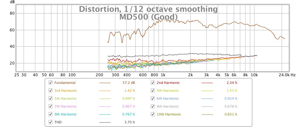
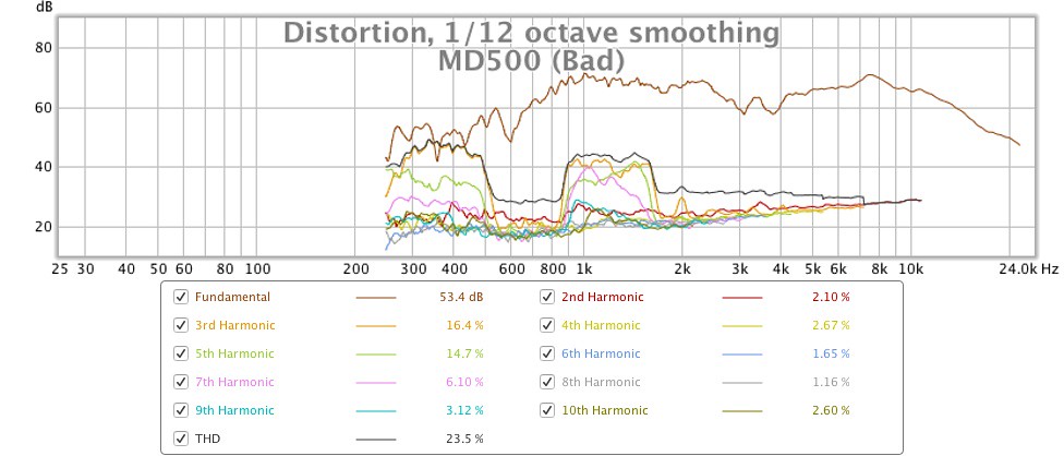
Unfortunately the partner to this M500 is faulty and in need of repair. It used to be a perfect sonic match, but after developing a buzz at the lower end of its operating range I sent it away around 10 years ago to a tech in Bournemouth, upon the recommendation of a trusted used hifi dealer from the same geographic location. I don’t know whether the tech dropped the unit on the floor or simply made a botch of the repair, but it came back sounding much quieter than before I sent it away, and it still had the same level of distortion if not more! Here are the raw frequency response graphs of the ‘good’ and ‘bad’ MD500s, as well as the respective distortion plots. I don’t know if it’s possible, but it would be awesome if I could find someone to repair the ‘bad’ unit and thus make it sound like the ‘good’ unit again. Is anyone on this forum able to repair an MD500?

The final compliment includes tweeters HF4 and HF7 which, despite measuring as somewhat of oddities with the first MF500 unit I picked, actually integrate very well with the final MF500s I installed and, aside from a divergence at 14kHz which will be inaudible to a lot of listeners, they track about 1dB across most of there operating range and, when played as a stereo pair, sound pretty much indistinguishable.
Likewise the mid and lower frequencies are also very well matched to around 1dB. I'm not quite sure of the reason for the difference in amplitude of the floor bounce null at 135Hz. One enclosure had a thicker than normal section of foam damping behind the bass driver (50mm instead of 40mm) so perhaps that's the cause?
I’ve learned more during this refurbishment than my previous two, having finally taken the opportunity to measure all of my spare MF500/MD500 and HF2000 units as part of the complete 66 system. Most surprising was the extent to which the HF2000 interacts with the upper (i.e. >1.5kHz) response of the MF500/MD500, and likewise the extent to which the MF500/MD500 interacts with the lower (i.e. <10kHz) response of the HF2000. It has now become obvious to me that pair-matching by only considering the driver’s responses in isolation does not guarantee a good result.
During my testing, I tried four T1600 bass drivers, six MF500 units, one MD500 unit, and thirteen HF2000 units. I noticed that regardless of the T1600 and MF500 combination used, this pair of 66s sounded consistently less coloured through the lower midrange and upper bass frequencies than my 2018 refurbished 66s. I’m curious as to why this is? The 2018 66s have measurably more lower midrange and bass output than my latest refurbishment, but we’re only talking about a difference of between 1dB and 2dB at most, and I wouldn’t have thought this would have much of an audible impact on the perceived clarity and colouration of the presentation.
If I apply a low-shelf filter EQ to my 2018 66s to reduce output by -2dB below 500Hz, their overall presentation does become clearer and less wooly and bloated and they sound much more like the 2019 66s, however they still don’t seem to have as much openness and dynamics. Do you think this could be due to my choice of capacitors? I really don’t want to go down the rabbit hole of “re-replacing” all of the caps, but is it wishful thinking that simply removing the parallel 1uf poly in the MF circuit will bring an improvement in openness, dynamics and transparency?
Interestingly, during my final stages of testing, I stumbled upon one particular driver combination that produced the best (i.e. clearest, smoothest, most transparent and dynamic) sound I have ever heard from a 66. I literally spent the entire night listening to it utterly captivated! This was achieved by pairing my only spare working MD500 driver with HF9. This MD500 in particular has approximately +2dB stronger output from 1kHz to 7kHz than any other MF500 or MD500 I have recently measured and, as you can see in the following graph, it integrates with HF9 superbly well. Again, there isn’t a great deal of measurable difference between it and my 2018 66, yet the difference is clearly audible to my ears.
Unfortunately the partner to this M500 is faulty and in need of repair. It used to be a perfect sonic match, but after developing a buzz at the lower end of its operating range I sent it away around 10 years ago to a tech in Bournemouth, upon the recommendation of a trusted used hifi dealer from the same geographic location. I don’t know whether the tech dropped the unit on the floor or simply made a botch of the repair, but it came back sounding much quieter than before I sent it away, and it still had the same level of distortion if not more! Here are the raw frequency response graphs of the ‘good’ and ‘bad’ MD500s, as well as the respective distortion plots. I don’t know if it’s possible, but it would be awesome if I could find someone to repair the ‘bad’ unit and thus make it sound like the ‘good’ unit again. Is anyone on this forum able to repair an MD500?
Last edited:
Hi again Alan,
I'm trying to understand why many folk choose to add a small value 'bypass' capacitor in parallel with the main large value capacitor/s in a loudspeaker crossover. One rationale seems to be that the bypass capacitor improves the discharge rate and transient response, which appears to be at odds with what you wrote in post #1241. See for example Capacitors in parallel | Audiokarma Home Audio Stereo Discussion Forums. I note that the discussion on that thread centres around the use of film caps as bypass caps, do these perform differently to poly caps (such as the Ansar SuperSound I've used) in terms of causing transient pulse errors?
Also, can you please explain why the HF section of the 66 crossover is made up of two (groups of) caps in series? Is it to create extra resistance to attenuate the HF output, or is this just how 3rd order crossover filters are constructed?
Last edited:
One Correction to my #1241, then responding to later Posts
Hello all ,
In my Post #1241 above I found I had written one mistake, as follows:
Where I wrote:
"But , when you change Polarity of Tweeter with respect to whichever Polarity the mid-dome is in the Vertical Off-Axis Nodes and Peaks swap around ,
and as result whichever polarity combination that causes a Peak to be directed upwards will cause worse audible problems from reflections from that top-lip of the enclosure."
-
The word "Nodes" should be "Nulls".
I was posting about vertical off-axis Lobes , which are Peaks and Nulls ,
but my brain got Lobes and Nulls mixed up and I wrote Nodes !
If there is any application for the word "Node" here it would be the Flat Response as measured on the optimum vertical axis for no Peaks or Nodes ,
but for now forget about "Node" as I will use the words Null and Peak for future posts here about vertical off-axis Lobes which occur at the crossover frequency as result of the Phase Lead and Phase Lag characteristics of the two respective arms' filters of the crossover network.
ToTo Man ,
you wrote:
"Despite being unable to hear tones above 13kHz, my own hearing is very acute and sensitive to channel imbalances, even on frequencies beyond 13kHz strangely enough!
I have therefore selected units to keep which have closely aligned responses throughout as much of the spectrum as possible."
Do not be surprised by that , as it is common.
In addition to hearing Amplitude Response many listeners also hear Phase Response , which in this case is the different Phase Responses of two tweeters that may have same Amplitude Response at 13kHz but if each has a substantially different Amplitude Response above 13kHz the Phase Shifts will be different for each at 13kHz and above.
There are obvious examples in your HF2000s amplitude responses of samples which will have quite different phase shifts throughout their measured spectrum.
Whenever there is a Change of Direction in amplitude response there is a change of Phase of a few degrees or more , dependent on magnitude and steepness of of amplitude changes.
Also , if the tweeters have different Impedance Curve shapes to each other throughout their measured amplitudes the Impedance differences also cause Phase differences ,
and those Impedance and Phase differences cause the one test sample crossover , or matched pair of crossovers , to produce the different results that you are hearing.
The above also applies to your mid-domes , which is why different samples of mid-domes are causing different audible results with different tweeters ,
even for mid-domes with similar measured amplitude responses because their relative Impedances may be different.
I refer you to the Impedance and Phase plots posted by sba on Page 36 in posts' #s 354 , 355 , 356.
Note also that the DC Resistance Magnitudes that sba listed in the Tables do not always correlate positively with Impedance Magnitudes ,
thus measured DC Resistance is only an estimate of what to expect for each sample.
With your Tweeters that have DC resistances that differ from lowest to highest in a Ratio of 3:4 that is the largest is 33% higher than the lowest , or the lowest is 25% lower than the highest ,
those are much larger differences than +/- 5% Tolerance capacitors differences between samples ,
thus expect all your tweeters to sound different when in your crossovers.
Similar will be the case with the Woofers , and one reason for the different Amplitudes you have measured and heard around the crossover frequency regions in your assembled 66s is the result of the above Impedance and Phase interactions between the driver for each frequency band.
I can hear Tones clearly to 16kHz at moderate Volume level , but above 16kHz my hearing drops off very sharply and no increase of Volume level allows me to hear any higher frequencies ,
but I do hear the higher frequencies modulating the System Noise
-{ the hiss , etc ... when I turn the volume up very loudly , and which if you try that then keep your hand on the volume knob and be ready to turn it down very quickly if any noise starts to suddenly increase in volume because it can cause damage to the drivers }.
I can see on your measurement plots how HF9 and HF11 form a close enough to Pair.
I had not looked for that previously because I was determined to find a match for HF1 as it has the closest to optimum frequency response for a good tweeter.
Which sample , if any , did you match by ear to HF1 ?
Also , did your hearing find sufficient match between HF2 and HF8 ? or have you matched either or both those to other samples ?
I'll reply to your later comments in the Quote Box below , with my responses indicated by -----> for each one.
Before I start what will likely have to be a very long Post to explain what I mean by Transient Pulse Distortion , and what some listeners are hearing with the 0.1uF Film capacitors connected in Parallel with either electrolytic caps or polypropylene caps , I advise you to do the listening experiments as above and report your audible findings.
A Third Order High-Pass Filter for a Passive crossover has two capacitors and one inductor placed in that T shape electrical connections circuit , such as is in all your 66s' tweeter filter sections.
P.S. addition: That old Orange Pye capacitor may have longer service life than the Elcaps ,
and the Elcap in parallel with it has significant Resistance within itself -{ ESR }- thus will not be causing any Transient Pulse Distortion.
Hello all ,
In my Post #1241 above I found I had written one mistake, as follows:
Where I wrote:
"But , when you change Polarity of Tweeter with respect to whichever Polarity the mid-dome is in the Vertical Off-Axis Nodes and Peaks swap around ,
and as result whichever polarity combination that causes a Peak to be directed upwards will cause worse audible problems from reflections from that top-lip of the enclosure."
-
The word "Nodes" should be "Nulls".
I was posting about vertical off-axis Lobes , which are Peaks and Nulls ,
but my brain got Lobes and Nulls mixed up and I wrote Nodes !
If there is any application for the word "Node" here it would be the Flat Response as measured on the optimum vertical axis for no Peaks or Nodes ,
but for now forget about "Node" as I will use the words Null and Peak for future posts here about vertical off-axis Lobes which occur at the crossover frequency as result of the Phase Lead and Phase Lag characteristics of the two respective arms' filters of the crossover network.
ToTo Man ,
you wrote:
"Despite being unable to hear tones above 13kHz, my own hearing is very acute and sensitive to channel imbalances, even on frequencies beyond 13kHz strangely enough!
I have therefore selected units to keep which have closely aligned responses throughout as much of the spectrum as possible."
Do not be surprised by that , as it is common.
In addition to hearing Amplitude Response many listeners also hear Phase Response , which in this case is the different Phase Responses of two tweeters that may have same Amplitude Response at 13kHz but if each has a substantially different Amplitude Response above 13kHz the Phase Shifts will be different for each at 13kHz and above.
There are obvious examples in your HF2000s amplitude responses of samples which will have quite different phase shifts throughout their measured spectrum.
Whenever there is a Change of Direction in amplitude response there is a change of Phase of a few degrees or more , dependent on magnitude and steepness of of amplitude changes.
Also , if the tweeters have different Impedance Curve shapes to each other throughout their measured amplitudes the Impedance differences also cause Phase differences ,
and those Impedance and Phase differences cause the one test sample crossover , or matched pair of crossovers , to produce the different results that you are hearing.
The above also applies to your mid-domes , which is why different samples of mid-domes are causing different audible results with different tweeters ,
even for mid-domes with similar measured amplitude responses because their relative Impedances may be different.
I refer you to the Impedance and Phase plots posted by sba on Page 36 in posts' #s 354 , 355 , 356.
Note also that the DC Resistance Magnitudes that sba listed in the Tables do not always correlate positively with Impedance Magnitudes ,
thus measured DC Resistance is only an estimate of what to expect for each sample.
With your Tweeters that have DC resistances that differ from lowest to highest in a Ratio of 3:4 that is the largest is 33% higher than the lowest , or the lowest is 25% lower than the highest ,
those are much larger differences than +/- 5% Tolerance capacitors differences between samples ,
thus expect all your tweeters to sound different when in your crossovers.
Similar will be the case with the Woofers , and one reason for the different Amplitudes you have measured and heard around the crossover frequency regions in your assembled 66s is the result of the above Impedance and Phase interactions between the driver for each frequency band.
I can hear Tones clearly to 16kHz at moderate Volume level , but above 16kHz my hearing drops off very sharply and no increase of Volume level allows me to hear any higher frequencies ,
but I do hear the higher frequencies modulating the System Noise
-{ the hiss , etc ... when I turn the volume up very loudly , and which if you try that then keep your hand on the volume knob and be ready to turn it down very quickly if any noise starts to suddenly increase in volume because it can cause damage to the drivers }.
I can see on your measurement plots how HF9 and HF11 form a close enough to Pair.
I had not looked for that previously because I was determined to find a match for HF1 as it has the closest to optimum frequency response for a good tweeter.
Which sample , if any , did you match by ear to HF1 ?
Also , did your hearing find sufficient match between HF2 and HF8 ? or have you matched either or both those to other samples ?
I'll reply to your later comments in the Quote Box below , with my responses indicated by -----> for each one.
My latest refurbished 66s are now with their new owner who will hopefully be delighted with his purchase given the amount of work I put in to them, particularly with regards to pair-matching the drivers!
The final compliment includes tweeters HF4 and HF7 which, despite measuring as somewhat of oddities with the first MF500 unit I picked, actually integrate very well with the final MF500s I installed and, aside from a divergence at 14kHz which will be inaudible to a lot of listeners, they track about 1dB across most of there operating range and, when played as a stereo pair, sound pretty much indistinguishable.
-----> I would readily hear the differences between HF4 and HF7 in the final results you posted the completed 66s' plots for , and for his sake I hope he can't , because if he can he will not be happy.
Really I think that HF7 is likely part-faulty and should not be sold except to a non-critical listener who simply wants a working HF2000 for an old loudspeaker to keep it usable for non-critical listening.
I'd have put HF5 in one of those , and then listened to the Pair of 66s with critical music for matching tweeter responses.
-----> HF5 doesn't seem to have any other match sample that looks closer to it than HF4 ... or did you hear a match sample for HF5 ?
---
Likewise the mid and lower frequencies are also very well matched to around 1dB. I'm not quite sure of the reason for the difference in amplitude of the floor bounce null at 135Hz. One enclosure had a thicker than normal section of foam damping behind the bass driver (50mm instead of 40mm) so perhaps that's the cause?
I’ve learned more during this refurbishment than my previous two, having finally taken the opportunity to measure all of my spare MF500/MD500 and HF2000 units as part of the complete 66 system. Most surprising was the extent to which the HF2000 interacts with the upper (i.e. >1.5kHz) response of the MF500/MD500, and likewise the extent to which the MF500/MD500 interacts with the lower (i.e. <10kHz) response of the HF2000. It has now become obvious to me that pair-matching by only considering the driver’s responses in isolation does not guarantee a good result.
-----> I have at least part-explained the reason for that in my preamble above.
---
During my testing, I tried four T1600 bass drivers, six MF500 units, one MD500 unit, and thirteen HF2000 units. I noticed that regardless of the T1600 and MF500 combination used, this pair of 66s sounded consistently less coloured through the lower midrange and upper bass frequencies than my 2018 refurbished 66s. I’m curious as to why this is? The 2018 66s have measurably more lower midrange and bass output than my latest refurbishment, but we’re only talking about a difference of between 1dB and 2dB at most, and I wouldn’t have thought this would have much of an audible impact on the perceived clarity and colouration of the presentation.
-----> the reason is likely that old capacitors' crossover , and which it seems from your later comments you are now suspecting also.
---
If I apply a low-shelf filter EQ to my 2018 66s to reduce output by -2dB below 500Hz, their overall presentation does become clearer and less woolly and bloated and they sound much more like the 2019 66s, however they still don’t seem to have as much openness and dynamics. Do you think this could be due to my choice of capacitors? I really don’t want to go down the rabbit hole of “re-replacing” all of the caps, but is it wishful thinking that simply removing the parallel 1uf poly in the MF circuit will bring an improvement in openness, dynamics and transparency?
-----> an Equalizer in circuit before the Amplifier to Loudspeakers will change Amplitudes but cannot change audible differences that are results of Resonances in the loudspeaker - those have to be dealt with within the loudspeaker itself - and the Equalizer itself causes other types of audible changes as you are now hearing.
As you seem to be a keen eared hearer then best is to experiment and listen , and then we'll discuss the technical reasons after you report what YOU can hear , as this is not primarily about what I can hear , but is primarily about what You can hear.
Thus , first remove the parallel Ansar Supercaps from BOTH your pairs of 66s' midrange circuits , and listen with only the effective 23.4uF and 26.4 approx uF E-caps in circuit.
If you prefer either or both , then Measure again , and on same mid-range axis as previously , or on whatever vertical axis that You find the sound makes the most coherent sense to you.
Next , but only after you listen to the 66s with only the mid-range filter section changed ,
for whichever pair of 66s you hear the most improvement take out the parallel 4.7uF and 1.5uF pair from the output of the tweeter section of the crossover and put back in those parallel four old pale green polyester capacitors
-{ if their sum together is close to 6uF , eg: between 5.8 and 6.4 }.
Those are plastic film capacitors and are very long life if they were manufactured without defect , and not later damaged by excess music signal level but which to do would also have blown the HF2000s at same time.
If you have those large black cylinder 2uF tweeter section capacitors still then measure those to find if still close to 6uF total , but do NOT use them if they measure more than 6.5uF together as they may then be faulty and will not sufficiently filter you old fragile tweeters.
I do not know for sure what those large black cylinder caps are ... but if you post here everything that is printed on them I might be able to identify them.
If they are old Paper-In-Oil types they have likely deteriorated too much to be safely useable.
Some 66s have a parallel pair of Olive green 4.7uF // 1.5uF in that section , but in Theory that combination should not sound as good as the other options ... if the other options are in good working condition.
Leave the Ansar Supersound 4uF capacitor in the tweeter filter section as it should not be part of the audible problem , unless one or more of them is a faulty sample.
---
Interestingly, during my final stages of testing, I stumbled upon one particular driver combination that produced the best (i.e. clearest, smoothest, most transparent and dynamic) sound I have ever heard from a 66. I literally spent the entire night listening to it utterly captivated! This was achieved by pairing my only spare working MD500 driver with HF9. This MD500 in particular has approximately +2dB stronger output from 1kHz to 7kHz than any other MF500 or MD500 I have recently measured and, as you can see in the following graph, it integrates with HF9 superbly well. Again, there isn’t a great deal of measurable difference between it and my 2018 66, yet the difference is clearly audible to my ears.
-----> I think what I have described so far answers at least one reason for that.
I recommend that you decide mid-domes by ear , and do not be concerned if you have one MD and one MF chosen by ear for a pair of 66s.
However do realize , for the Impedance and Phase reasons I explained above , that some of the mid-domes may work better with the 23.4uF capacitor and others may work better with the summed three to 26.4uF capacitor.
Keep the Volume moderate and try all combinations by ear , but reduce Volume if you hear any of the mid-domes starting to distort when in the 26.4uF 66s.
---
Unfortunately the partner to this M500 is faulty and in need of repair. It used to be a perfect sonic match, but after developing a buzz at the lower end of its operating range I sent it away around 10 years ago to a tech in Bournemouth, upon the recommendation of a trusted used hifi dealer from the same geographic location. I don’t know whether the tech dropped the unit on the floor or simply made a botch of the repair, but it came back sounding much quieter than before I sent it away, and it still had the same level of distortion if not more! Here are the raw frequency response graphs of the ‘good’ and ‘bad’ MD500s, as well as the respective distortion plots. I don’t know if it’s possible, but it would be awesome if I could find someone to repair the ‘bad’ unit and thus make it sound like the ‘good’ unit again. Is anyone on this forum able to repair an MD500?
-----> from your plots I think it likely that the voice-coil of the repaired sample has not been correctly centered or other correctly placed within the magnet gap.
There is a repairer of MD , and possible MF , domes in France.
If you are interested I'll post more about that later.
I saw in your other posts that you have measured the mid-domes Distortion from 250Hz upwards.
I am very impressed that those old domes have such low distortion in the 250Hz to 400Hz region , as that indicates very good design and construction.
I had expected to see some distortion in that region , but not as much as in the faulty sample MD.
Did you do those tests at low signal level or medium signal level , by which I mean were the tests done at a signal level that you would use for normal music listening or at much lower level ?
---
Before I start what will likely have to be a very long Post to explain what I mean by Transient Pulse Distortion , and what some listeners are hearing with the 0.1uF Film capacitors connected in Parallel with either electrolytic caps or polypropylene caps , I advise you to do the listening experiments as above and report your audible findings.
A Third Order High-Pass Filter for a Passive crossover has two capacitors and one inductor placed in that T shape electrical connections circuit , such as is in all your 66s' tweeter filter sections.
P.S. addition: That old Orange Pye capacitor may have longer service life than the Elcaps ,
and the Elcap in parallel with it has significant Resistance within itself -{ ESR }- thus will not be causing any Transient Pulse Distortion.
Last edited:
Hi Alan,
In Post #1238 I assumed the small ripples before the first peak in the Step Response were part of the signal going to the DUT. After reading up on the various software packages I realised they do not send any signal to improve the measurement quality (other than Speaker Workshop).
The ripples appear to be a fairly normal part of the impulse response and are present in varying degrees depending on the converter (sound card), DUT and perhaps the software processing method. This post discusses some of the issues:
Impulse response
In looking at Impulse Responses from my own tests the ripple (or pre-ringing) is there in most results. Some old results using Speaker Workshop also have the ringing in a tweeter test (Vifa), a smaller ringing in the MF500 and none in a 10" woofer.
I also noticed a smaller replica pulse at about -2 mS to -3 mS before the main impulse peak when using my external audio interface similar to the result shown in this ARTA thread at #801:
https://www.diyaudio.com/forums/multi-way/76977-arta-81.html#post5775688
Seems that this could be due to crosstalk between the channels. May have to look at a different interface.
Hi Alan,
HF1 was tricky to match using the first mid driver I used as a control sample for all tweeter measurements, as HF1 has comparatively lower output between 4kHz-8kHz than the other tweeters measured. Based on that particular mid driver, HF1 pairs closest with HF9 or HF11 according to FR response measurements. Again, this is based solely on one particular mid driver, one particular measurement distance, and one particular measurement height, and could very easily change with any of these variables.
It has been suggested on another forum that the veneered baffles on my 2018 66s may potentially be a source of colouration, as the added stiffness could in theory be pushing resonances higher up into the audible band compared to the 66s with black baffles. This isn't something I'd considered. Does this sound plausible, or are the resonances you refer to more likely to be arising from the drivers and/or crossover design regardless of the enclosure?
I still have the old caps from my respective 2015 and 2018 refurbs in a box somewhere. The 2015 crossovers had the large black cylindrical caps in the HF section, one crossover had an orange Pye and small Elcap in the MF section while the other just had one large Elcap.
The 2018 crossovers had the banks of green film polyester caps in the HF section and one large Elcap in the MF section. The audio output from the 2015 crossovers was intermittent and was affected by squeezing the group of black cylindrical HF caps. I’m not sure if the caps were bad or if it was just bad solder joints, but that was the main reason for re-capping the 2015 crossovers.
I recapped the 2018 crossovers as a precautionary measure due to the development of a buzz in an MD500 driver and elevated levels of distortion in an HF2000, but do not know if this was directly caused by the caps or by the previous owner misusing the speakers. I need to buy a proper capacitance meter, the only one I have is part of my Precision Gold WG 020 ohmmeter and it will only measure a cap if the metal leads are long enough to reach all of the way inside to the contact plates. This makes measuring old caps with cut wires very difficult!
Last night I reclaimed my 2015 refurb'd 66s from storage to perform some critical listening. This pair sounds very articulate, very similar to the 2019 pair I just refurb'd, and do not possess the upper bass / lower midrange colouration of my 2018 pair, yet they have been re-capped with exactly the same capacitor complement (apart from the 24uf/30uf difference in the MF filter). Thus, before I remove or swap out any caps, I think I’m going to swap the T2169 drivers for T1600 drivers, and then swap the MD500 units for MF500 units, to see if any of those changes resolve the colouration.
Which sample , if any , did you match by ear to HF1 ?
HF1 was tricky to match using the first mid driver I used as a control sample for all tweeter measurements, as HF1 has comparatively lower output between 4kHz-8kHz than the other tweeters measured. Based on that particular mid driver, HF1 pairs closest with HF9 or HF11 according to FR response measurements. Again, this is based solely on one particular mid driver, one particular measurement distance, and one particular measurement height, and could very easily change with any of these variables.
My auditory memory of the pairings is now fading so I cannot recall with confidence which pairs sounded best with each other, but I seem to recall being convinced by HF2 + HF5 more than by HF2 + HF8. HF8 sounded a bit crisper than HF5, presumably owing to its 2.5dB higher output between 8kHz-12kHz. I have generated graphs of all the potential HF2000 pairings based on frequency response. I can post these if they'd be of interest?did your hearing find sufficient match between HF2 and HF8 ? or have you matched either or both those to other samples ?
Similar will be the case with the Woofers , and one reason for the different Amplitudes you have measured and heard around the crossover frequency regions in your assembled 66s is the result of the above Impedance and Phase interactions between the driver for each frequency band.
an Equalizer in circuit before the Amplifier to Loudspeakers will change Amplitudes but cannot change audible differences that are results of Resonances in the loudspeaker - those have to be dealt with within the loudspeaker itself - and the Equalizer itself causes other types of audible changes as you are now hearing.
It has been suggested on another forum that the veneered baffles on my 2018 66s may potentially be a source of colouration, as the added stiffness could in theory be pushing resonances higher up into the audible band compared to the 66s with black baffles. This isn't something I'd considered. Does this sound plausible, or are the resonances you refer to more likely to be arising from the drivers and/or crossover design regardless of the enclosure?
first remove the parallel Ansar Supercaps from BOTH your pairs of 66s' midrange circuits , and listen with only the effective 23.4uF and 26.4 approx uF E-caps in circuit. If you prefer either or both , then Measure again , and on same mid-range axis as previously , or on whatever vertical axis that You find the sound makes the most coherent sense to you.
Next , but only after you listen to the 66s with only the mid-range filter section changed , for whichever pair of 66s you hear the most improvement take out the parallel 4.7uF and 1.5uF pair from the output of the tweeter section of the crossover and put back in those parallel four old pale green polyester capacitors { if their sum together is close to 6uF , eg: between 5.8 and 6.4 }.
Those are plastic film capacitors and are very long life if they were manufactured without defect , and not later damaged by excess music signal level but which to do would also have blown the HF2000s at same time.
If you have those large black cylinder 2uF tweeter section capacitors still then measure those to find if still close to 6uF total , but do NOT use them if they measure more than 6.5uF together as they may then be faulty and will not sufficiently filter you old fragile tweeters.
I do not know for sure what those large black cylinder caps are ... but if you post here everything that is printed on them I might be able to identify them.
If they are old Paper-In-Oil types they have likely deteriorated too much to be safely useable.
P.S. That old Orange Pye capacitor may have longer service life than the Elcaps ,
and the Elcap in parallel with it has significant Resistance within itself -{ ESR }- thus will not be causing any Transient Pulse Distortion.
I still have the old caps from my respective 2015 and 2018 refurbs in a box somewhere. The 2015 crossovers had the large black cylindrical caps in the HF section, one crossover had an orange Pye and small Elcap in the MF section while the other just had one large Elcap.
The 2018 crossovers had the banks of green film polyester caps in the HF section and one large Elcap in the MF section. The audio output from the 2015 crossovers was intermittent and was affected by squeezing the group of black cylindrical HF caps. I’m not sure if the caps were bad or if it was just bad solder joints, but that was the main reason for re-capping the 2015 crossovers.
I recapped the 2018 crossovers as a precautionary measure due to the development of a buzz in an MD500 driver and elevated levels of distortion in an HF2000, but do not know if this was directly caused by the caps or by the previous owner misusing the speakers. I need to buy a proper capacitance meter, the only one I have is part of my Precision Gold WG 020 ohmmeter and it will only measure a cap if the metal leads are long enough to reach all of the way inside to the contact plates. This makes measuring old caps with cut wires very difficult!
Last night I reclaimed my 2015 refurb'd 66s from storage to perform some critical listening. This pair sounds very articulate, very similar to the 2019 pair I just refurb'd, and do not possess the upper bass / lower midrange colouration of my 2018 pair, yet they have been re-capped with exactly the same capacitor complement (apart from the 24uf/30uf difference in the MF filter). Thus, before I remove or swap out any caps, I think I’m going to swap the T2169 drivers for T1600 drivers, and then swap the MD500 units for MF500 units, to see if any of those changes resolve the colouration.
I think I know who you are referring to, does he advertise his services on eBay? Have any forum members used him before? It would be good to hear feedback.P.S. from your plots I think it likely that the voice-coil of the repaired sample has not been correctly centered or other correctly placed within the magnet gap.
There is a repairer of MD , and possible MF , domes in France.
If you are interested I'll post more about that later.
The sweeps were performed at the levels shown on the graphs' Y-axis, i.e. around 65dB-70dB measured at 1 metre distance. I'm probably being overcautious but I don't like running tests loudly, especially on drivers with no crossover connected, for fear of damage occurring.I saw in your other posts that you have measured the mid-domes Distortion from 250Hz upwards.
I am very impressed that those old domes have such low distortion in the 250Hz to 400Hz region , as that indicates very good design and construction.
I had expected to see some distortion in that region , but not as much as in the faulty sample MD.
Did you do those tests at low signal level or medium signal level , by which I mean were the tests done at a signal level that you would use for normal music listening or at much lower level ?
Last edited:
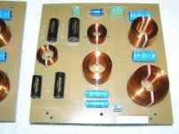
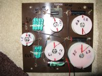
Allan: new caps went into my homemade DIY xovers. Didnt want to *lose* the originals. Also have a set from France (Amocom) They make upper freq more pronounced. ( I think).
Pics of all 3 sets included.
Coils are Jantzen: 3.5mH,1.1ohm, 18awg
2.2mH, .84ohm, 18awg
.35mH , .4ohm, 20awg
.15mH, .23ohm, 20awg
Eloctrlytics are Alcap, rest are Clarity.
Should be done building in a day or 2, so not tested yet.
Also cot a new voice coil from France for my spare MD500, not installed yet
Attachments

Last edited:
Some responses since my last post
Hi Doug ,
OK , you have two somewhat different new crossovers ,
thus after you have done some time of listening to each of them please Post here about the differences you found you could hear between each of them ,
because that could be interesting , and useful to readers of this thread.
---
Hi DennyG , and ToTo Man ,
I'll go back first to DennyG's Post #1213 , and proceed from there through his Posts with some comments relevant to what is practical to expect from Celestion 66s.
Of those two MF domes in #1213 , the Blue one seems fairly normal , and useable , with its only minor fault being the approximately +2dB peak around 8kHz -{ +2dB wrt its otherwise output in its upper frequencies response }-
which appears as approximately +3dB wrt the Green MF dome , but the Green MF being less output overall is likely a less useful sample.
Note also , the Green MF has a significantly higher frequency Fs than the Blue , and also than DennyG's other mid-domes , and than most of sba's mid-domes.
That indicates a stiffer suspension , and which may be the reason it has lower output at higher frequencies ... I would be wary of that MF until I at least listened to it.
Also , see in the #1218 Step Responses that the Blue has less Amplitude than the Green - that indicates that the Blue's dome is better controlled by its Magnet and suspension than the Green.
Given the amplitude humps of both samples around approximately 1.2kHz I think the 24uF capacitor option would be better than the 30uF capacitor option for both those mid-domes ,
unless that 1.2kHz high is result of the shape of the test enclosure.
Posts #1219 and #1238 and #1246 , and including in Links to the other threads there-in ,
all have information which confirms to me the problems with using Digital test equipment ... that being that one has to get the test equipment to work without it interfering with what one is trying to measure ... all of which would frustrate me to almost no end !
Thus I may as well state now that:
(1)- Step Response is of little use in evaluating a Celestion 66 because:
(a)- the Tweeter and the ABR operate in Reverse Polarity to the Woofer and Mid-dome , thus the Step Response is pushed Up and Down when each change of Polarity is detected.
(b)- the 4th Order crossover section to the woofer resonates at the 500Hz crossover frequency , and the Band-Pass filter to the mid-dome has an internal Resonance of its own somewhere between 500Hz and 5kHz.
Both those Resonances affect the Step Response , as also does the 3rd Order filter section to the tweeter.
(c)- the Vertical Axis chosen to measure on can only be of equal arrival time for two of the drivers at most , as all four drivers including the ABR are located at different points in space.
Note the simpler Step Response for ToTo Man's Tannoy which has both drivers with their centers at the same point in space , even though the Tweeter is delayed in Time behind the Woofer.
For Celestion 66 I think Step Response will be useful only to show some characteristics of each driver when each is tested separately and without any crossover connected.
Thus for any drivers that may be of suspect condition , do Step Responses of them and also of drivers which seem to not be of suspect condition , and compare the results.
(2)- Impulse Response can be used with separate drivers without crossover for comparing drivers' condition also.
And , Impulse Response can also be used to find an equal signal time arrival vertical height to find the optimum vertical listening axis for the complete 66.
Celestion's engineers would have known that all three active drivers + ABR were not Time Aligned , thus my estimate is they may have designed the crossover to include best coherence though the 5kHz changeover ,
and then compensated with choice of inductors and capacitors for the 500Hz changeover for there to not be a large vertical off-axis notch-out around 500Hz when listening at whatever was chosen as the recommended distance from loudspeaker to listener ,
and likely that was about 6 Feet , which is now close enough to 2 metres.
I see in some of ToTo Man's full system frequency response plots that there is notch-out in the 700Hz region ,
thus is that result of not measuring on Celestion's chosen Vertical Axis and not at Celestion's measuring distance from the loudspeaker ?
... or is that result of something in ToTo Man's test room ?
ToTo Man has already - mostly in the other Forum - described the audible effects of different listening heights , thus we can continue with that here ,
and for that I will post how to use Impulse Response to find the equal arrival time from Tweeter and Mid-dome , and at a decided listening distance ,
but not today as I do not have sufficient time now ,
however I suggest now that a listening distance be decided by each interested Tester so that I can refer to that.
ToTo Man , after you have done more of the drivers' swapping and listening in the different cabinets and reported here we can proceed with more about the drivers and crossovers.
For now I state that cabinets with hard-wood veneered surfaces will have higher frequency resonances in those panels than otherwise identical cabinets which do not have the hard-wood veneered panels ,
however the amplitudes of the resonances will be approximately the same for both types of cabinets , except if the resonances of any of the non-veneered panels common to BOTH cabinet types happen to cause larger amplitude resonance by co-incidence in the non-veneered cabinet.
Moermusic has identified one French seller of parts for MD500 , but I'm not sure if that is the same person who does the repairs.
There was an MD500 repairer mentioned in one of the several Celestion 66 threads of this Forum , but I have forgotten which and where.
I'll look for the ebay Seller before I return to post more in this thread.
Last edited:
Hi Alan,
Responding to your comments in post #1241 regarding driver polarity, if reversing the phase of the mid with respect to the woofer produces a subjectively preferable output to my ears at the LF/MF crossover point, can you please advise the best way to achieve this with respect to minimising any adverse impacts elsewhere in the response? For example:
1) If I reverse the polarity of the woofer with respect to the mid, does this produce the same result as reversing the polarity of both the mid and tweeter with respect to the woofer?
2) If I reverse the polarity of the woofer, and then reverse the polarity of the entire speaker at the amplifier speaker output, presumably this produces the same result as simply reversing the polarity of both the mid and tweeter?
Allan: new caps went into my homemade DIY xovers. Didnt want to *lose* the originals. Also have a set from France (Amocom) They make upper freq more pronounced. ( I think).
Pics of all 3 sets included.
Coils are Jantzen: 3.5mH,1.1ohm, 18awg
2.2mH, .84ohm, 18awg
.35mH , .4ohm, 20awg
.15mH, .23ohm, 20awg
Eloctrlytics are Alcap, rest are Clarity.
Should be done building in a day or 2, so not tested yet.
Also cot a new voice coil from France for my spare MD500, not installed yet
I'm interested to hear your thoughts on how your three crossovers compare?
Response to #1250 and earlier
'ullo ToTo Man ,
As replies to your most recent two questions I state:
1) Maybe ... as the two options seem to depend on how any particular listener's ear/brain mechanism works.
Some listeners hear only Relative Polarity , thus could reverse to Woofer and leave the other two as original , or leave the Woofer as original and reverse the other two , and apparently that type of listener hears both options the same - no difference ,
however some listeners report hearing Absolute Polarity , that is they hear when a loudspeaker driver pushes in response to a Positive leading signal pulse as different to when they hear the same driver and signal with the reverse polarity connection which causes an initial pull or suck-in.
It seems to me I hear Absolute Polarity , but I have not done recent testing of that as I always listen with Positive Polarity connections , but many years ago I did hear the differences through a single loudspeaker driver when it was connected to an an amplifier that had one channel connected in Positive polarity and the other channel connected in Reverse Polarity ... I was listening in Mono only and with a single wide-range speaker driver which by coincidence I heard a difference when I had it connected to one channel of the amplifier than when I tried the same diver connected to the other channel -{ of the same amplifier }.
At that time I did NOT know that one channel of the amplifier had inverted the Polarity - I found that years later when I returned to investigate the internal circuit of the amplifier.
You will have to try both options of connection to find if you can hear any difference.
Also , if you can hear a difference then you may prefer the Positive connection driver to be the one that contains the frequency band information that you most focus on - and maybe that will be the mid-dome , but alternately maybe you will prefer the mid-range information presented in Reverse Polarity aand Bass information in Positive polarity.
Also , it may change depending on the type of Music , eg: different with percussion instruments music to music that does not require percussion.
2) usually Yes , but possibly not if the amplifier has a significant DC offset voltage -{ of similar magnitudes in both channels }- because that would set the voice-coil of the Woofer to start from the opposite off-set position.
Use the DC Volts range of a Multimeter and measure accross the loudspeaker terminals of your amplifier with Power On but no signal though the amplifier.
Measure both with and without the loudspeakers connected as there can be a different Magnitude of DC voltage offset with versus without a Load connected.
Up to about 5mV is not a problem , nor even up to around 10mV , and plenty of amplifiers sound OK with up to about 20mV , but if more than that I think something in the circuitry will be out-of-alignment , and likely cause audible results to a sensitive Woofer when trying the alternate polarities' listening.
DC offsets will not get to midrange drivers nor tweeters unless the crossover capacitors are leaking charge ,
and small DC offsets do cause mid-domes and tweeters to sound less than their best through leaky capacitors.
---
About where you stated:
"Last night I reclaimed my 2015 refurb'd 66s from storage to perform some critical listening. This pair sounds very articulate, very similar to the 2019 pair I just refurb'd, and do not possess the upper bass / lower midrange colouration of my 2018 pair, yet they have been re-capped with exactly the same capacitor complement (apart from the 24uf/30uf difference in the MF filter). Thus, before I remove or swap out any caps, I think I’m going to swap the T2169 drivers for T1600 drivers, and then swap the MD500 units for MF500 units, to see if any of those changes resolve the colouration."
I ask: which pair have 24uF and which pair have 30uF respectively to the midrange circuit ?
And , did the third pair , which you sold , have 24uF or 30uF when you did your final test listening before selling them.
---
The French seller of supposedly Vintage Celestion parts that I have found on ebay is:
ninomusicfrance
and after Google search I found a web-site:
Ninomusic
but it is not fully functioning , however on the ebay screen there was a Notice that the Seller is away until 17th June.
I also found that there is apparently a Chinese manufactured Dome being sold for MD500 and MF500 dome replacement.
It is brown coloured , and thus may be made of Phenolic as Phenolic was used for the Dome drivers for mid and treble Horns before the Metal dome era , and some Phenolic domes are still in use.
I do not know if Celestion used the same Dome for their MD and MF direct radiators as was used as Horn drivers in that era , and if they didn't I would be suspicious of fitting a Horn driver to a direct radiator midrange , but it is possible for the same dome to be able to work in both acoustic environments , however I do not know if equally good performance in both -{ and ignoring the increased efficiency when attached to a Horn }.
'ullo ToTo Man ,
As replies to your most recent two questions I state:
1) Maybe ... as the two options seem to depend on how any particular listener's ear/brain mechanism works.
Some listeners hear only Relative Polarity , thus could reverse to Woofer and leave the other two as original , or leave the Woofer as original and reverse the other two , and apparently that type of listener hears both options the same - no difference ,
however some listeners report hearing Absolute Polarity , that is they hear when a loudspeaker driver pushes in response to a Positive leading signal pulse as different to when they hear the same driver and signal with the reverse polarity connection which causes an initial pull or suck-in.
It seems to me I hear Absolute Polarity , but I have not done recent testing of that as I always listen with Positive Polarity connections , but many years ago I did hear the differences through a single loudspeaker driver when it was connected to an an amplifier that had one channel connected in Positive polarity and the other channel connected in Reverse Polarity ... I was listening in Mono only and with a single wide-range speaker driver which by coincidence I heard a difference when I had it connected to one channel of the amplifier than when I tried the same diver connected to the other channel -{ of the same amplifier }.
At that time I did NOT know that one channel of the amplifier had inverted the Polarity - I found that years later when I returned to investigate the internal circuit of the amplifier.
You will have to try both options of connection to find if you can hear any difference.
Also , if you can hear a difference then you may prefer the Positive connection driver to be the one that contains the frequency band information that you most focus on - and maybe that will be the mid-dome , but alternately maybe you will prefer the mid-range information presented in Reverse Polarity aand Bass information in Positive polarity.
Also , it may change depending on the type of Music , eg: different with percussion instruments music to music that does not require percussion.
2) usually Yes , but possibly not if the amplifier has a significant DC offset voltage -{ of similar magnitudes in both channels }- because that would set the voice-coil of the Woofer to start from the opposite off-set position.
Use the DC Volts range of a Multimeter and measure accross the loudspeaker terminals of your amplifier with Power On but no signal though the amplifier.
Measure both with and without the loudspeakers connected as there can be a different Magnitude of DC voltage offset with versus without a Load connected.
Up to about 5mV is not a problem , nor even up to around 10mV , and plenty of amplifiers sound OK with up to about 20mV , but if more than that I think something in the circuitry will be out-of-alignment , and likely cause audible results to a sensitive Woofer when trying the alternate polarities' listening.
DC offsets will not get to midrange drivers nor tweeters unless the crossover capacitors are leaking charge ,
and small DC offsets do cause mid-domes and tweeters to sound less than their best through leaky capacitors.
Thank you for these insights Alan, looks like I have some further experimenting to do! 🙂
My 2015 (black fronted) refurb'd 66s have 30uf and my 2018 (veneer fronted) refurb'd 66s have 24uf. The 2019 refurb'd 66s I just sold (to the best of my knowledge) had 30uf in both crossovers. I say "to the best of my knowledge" because one crossover had one orange Pye cap and one 6uf Elcap, while the other crossover had two orange Pye caps and one 6uf Elcap. The Pye caps were positioned such that I could not see the capacitance values printed on them, thus I am making the assumption, based on the presence of a 6uf Elcap on each crossover, that the single Pye cap was 24uf and the twin Pye caps were 12uf each.About where you stated:
"Last night I reclaimed my 2015 refurb'd 66s from storage to perform some critical listening. This pair sounds very articulate, very similar to the 2019 pair I just refurb'd, and do not possess the upper bass / lower midrange colouration of my 2018 pair, yet they have been re-capped with exactly the same capacitor complement (apart from the 24uf/30uf difference in the MF filter). Thus, before I remove or swap out any caps, I think I’m going to swap the T2169 drivers for T1600 drivers, and then swap the MD500 units for MF500 units, to see if any of those changes resolve the colouration."
I ask: which pair have 24uF and which pair have 30uF respectively to the midrange circuit ?
And , did the third pair , which you sold , have 24uF or 30uF when you did your final test listening before selling them.
Since our last correspondence I have made some progress with 'troubleshooting' my 2018 refurb'd 66s. I swapped out the T2169 bass drivers for T1600 bass drivers and the frequency response below 500Hz has subjectively and measurably become closer to that of my 2015 refurb'd 66s. The differences that remain between 600Hz-900Hz must therefore be entirely mid unit related.
Before:
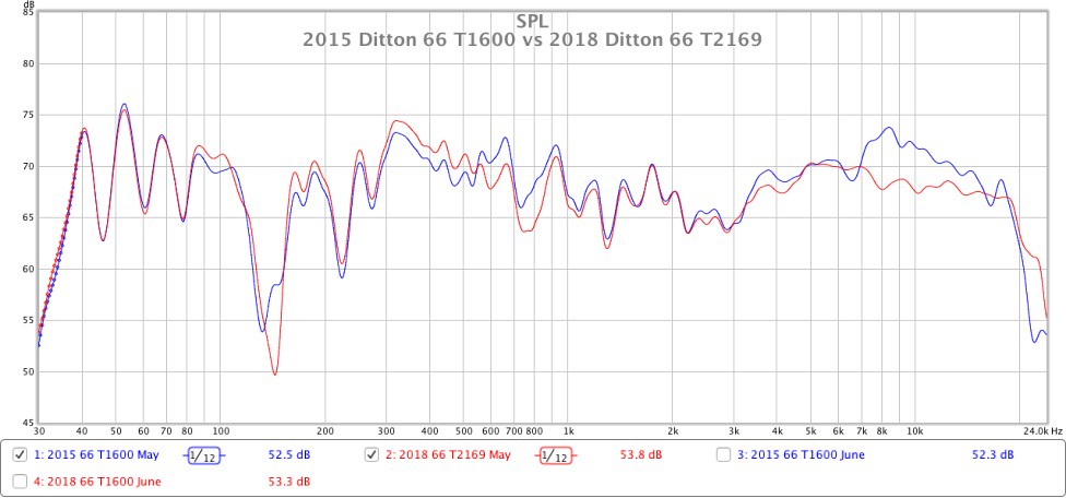
After:
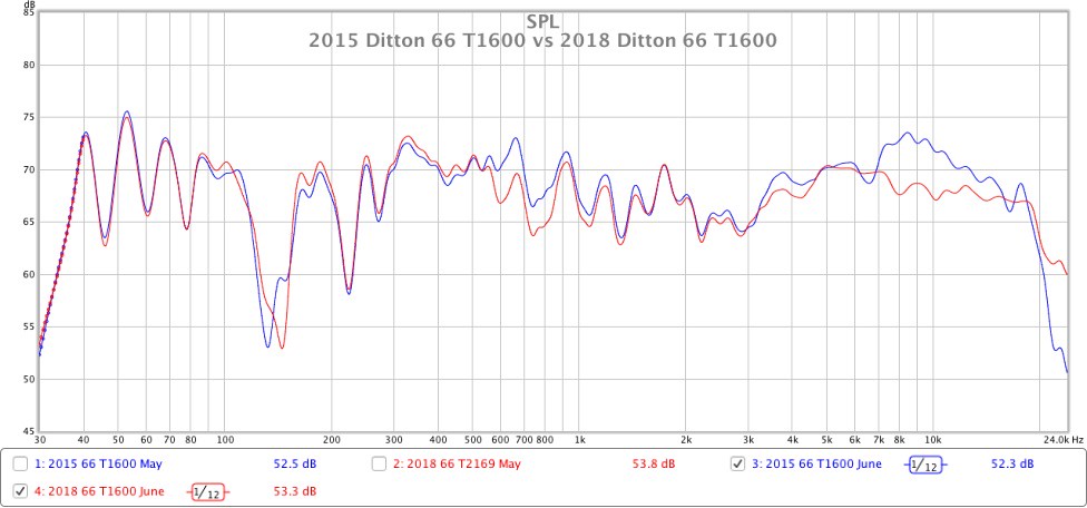
PS - As you can see in the graphs, there is a significant difference in HF response between the 2015 and 2018 66s. This makes focusing on the LF/MF responses quite challenging as the ear is easily led astray by response differences elsewhere. Thus, whenever I compare the two speakers I apply a notch filter at 9kHz to the 2015 66 to make its HF response match the 2018 refurb. I will eventually replace the HF2000s in the 2015 66s for ones that aren’t quite so ‘hot’, but that’s a job for another day.
The French seller of supposedly Vintage Celestion parts that I have found on ebay is:
ninomusicfrance
and after Google search I found a web-site:
Ninomusic
but it is not fully functioning , however on the ebay screen there was a Notice that the Seller is away until 17th June.
I also found that there is apparently a Chinese manufactured Dome being sold for MD500 and MF500 dome replacement.
It is brown coloured , and thus may be made of Phenolic as Phenolic was used for the Dome drivers for mid and treble Horns before the Metal dome era , and some Phenolic domes are still in use.
I do not know if Celestion used the same Dome for their MD and MF direct radiators as was used as Horn drivers in that era , and if they didn't I would be suspicious of fitting a Horn driver to a direct radiator midrange , but it is possible for the same dome to be able to work in both acoustic environments , however I do not know if equally good performance in both -{ and ignoring the increased efficiency when attached to a Horn }.
Thanks for this info, I’ll look into it.
Sorry, but i'm going to ask off topic question to all you celestion lovers;
Anyone knows anything about ditton 332-442 etc series crossovers.
Especially about any reverse polarity connected drivers? Or all drivers connected in phase?
Anyone knows anything about ditton 332-442 etc series crossovers.
Especially about any reverse polarity connected drivers? Or all drivers connected in phase?
With the T2169 woofers in both of my 2018 refurb'd 66s now replaced with T1600 units that are a very close response match to the T1600s in my 2015 refurb'd 66s, I decided to reverse the polarity of one woofer to see what effect this has. The results are as follows. (Again, all measurements were made at a distance of 1 metre and on-axis with the MD500 unit, so may not be relevant for farfield distances).
Amplitude frequency responses:
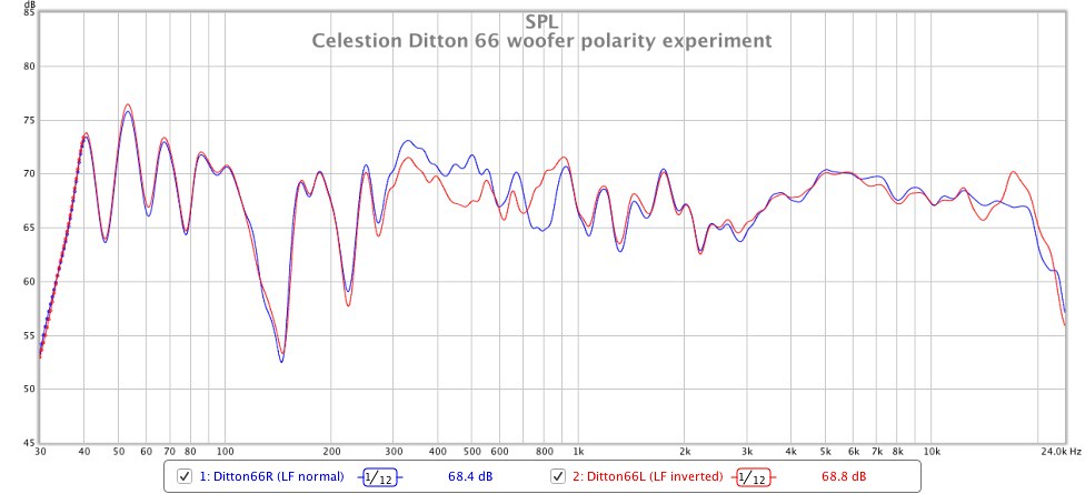
Phase responses:
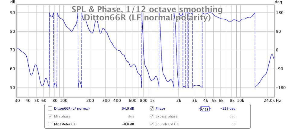
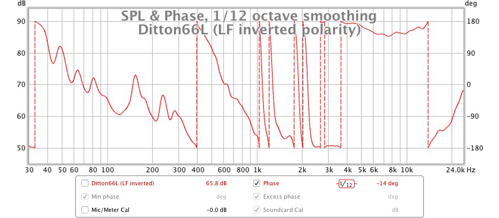
Step responses:
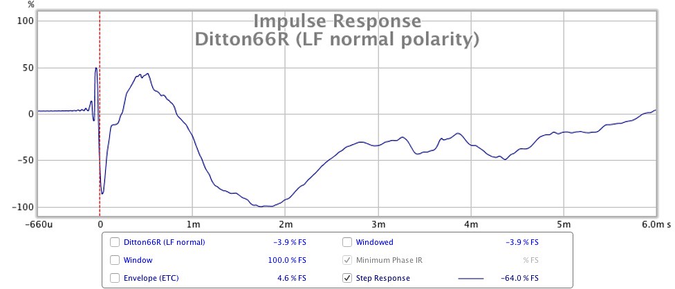
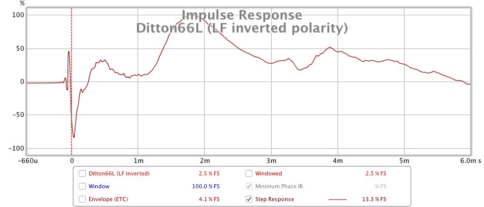
The difference in the amplitude frequency response is pretty self-explanatory; there is decreased output between 300Hz-550Hz and increased output between 700Hz-900Hz. The mid-range sounds more forward with less upper-bass bleed when the woofer's polarity is inverted, I think I prefer this new tonal balance.
Regarding the Phase Response and Step Response graphs, I could use a little help to explain the changes in those! 🙂
Amplitude frequency responses:
Phase responses:
Step responses:
The difference in the amplitude frequency response is pretty self-explanatory; there is decreased output between 300Hz-550Hz and increased output between 700Hz-900Hz. The mid-range sounds more forward with less upper-bass bleed when the woofer's polarity is inverted, I think I prefer this new tonal balance.
Regarding the Phase Response and Step Response graphs, I could use a little help to explain the changes in those! 🙂
Last edited:
I'm interested to hear your thoughts on how your three crossovers compare?
hearing test of my 3 crossovers:
test apparatus - 2 pair 70 yr old ears
New British built vs my new DIYers: neither of us could hear any appreciable differences
British built vs originals: bass on the new seems a bit behind the mid & upper. ie the upper freq's are much crisper & more prominent than the bass. bass on the originals appears to be a bit more prominent than the upper freq's. Perhaps all due to the new caps. I cant be sure if one sounded more prominent than the other when units were new in 1977, & prob didnt care when 27 yrs old.
think I could listen to all 3 different sets with no trouble.
left spkr had new British xover, while right spkr had xovers switched out, so side by side comparison, in left & right mono, alternating left-right spkrs.
sure would be *easy* if xovers had spade terminals for driver wires, vs clips holding everything together.
responses to: #1254 - starbender , and #1256 moermusic
Hi starbender ,
I remember when 442 , 551 , 662 models were released which was quite a number of years after the two versions of 44 and 66 -{ there was no previous 55 model }- ,
and 332 was soon after 442.
551 and 442 were fairly well received by the Hi-Fi Press , but less so for 662 , and I do not remember the response to 332.
442 and 662 are more than a little different to 44 and 66 , thus likely 332 is audibly noticeably different to original 33 ,
but as all were 3-way it is likely the Tweeters were connected in Negative Polarity versus Mid-drivers in Positive Polarity , as with the previous series.
Celestion used to supply crossover schematics to Owners who wanted to re-condition their 44s and 66s , thus I suppose Celestion would have supplied schematics for 332 and 442 , etc ...
but now that Celestion is owned by the Asian Gold Peak Industries I do not know if they will supply schematics.
I suggest you email to the British Celestion address , and not to the International nor Asian , and ask for schematics , and offer to pay for cost of finding and sending -{ as that demonstrates Respect and Goodwill }- and wait to find if any response.
If your loudspeakers have Serial Numbers printed on the backs of the cabinets then quote those in your query as that indicates that you are a Celestion Owner , and then there would be greater likelihood of a positive reply.
Also , post a Celestion 332 and 442 Thread in diyAudio and ask there ,
and if Celestion later send schematics , then post those in your thread because that helps other Owners , plus may cause some interesting discussion about re-conditioning -{ like the huge amount in this 66 thread ! }.
--- --- ---
Hi moermusic ,
I am surprised that you are not hearing "appreciable differences" between your DIY crossover and that pre-assembled one you bought ... I think I would ,
however a better way is to listen for a few weeks with one crossover to a wide variety of music , and then install the other crossover and listen to the same selections of music.
Your Moods may be different during the relative periods , but should even out a bit over two weeks or longer ,
thus perhaps overall you may then hear how one crossover presents some details differently to the other.
There should be differences in both the Treble details and the Bass details ,
albeit depending on how loudly you drive the speakers ,
as when played quietly the Bass details in particular may sound same with both crossovers.
When listening quietly the Midrange will likely be the dominant influence on your hearing.
When played loudly the differences between the different Inductors should be audible ,
but do NOT concentrate on hearing differences , instead focus on hearing how the Music is performed
- that is: allow your brain to interpret the Performance of Music , then any audible differences will become meaningful.
responses to ToTo Man
Hi ToTo Man ,
in #1211 on page 122 , you noted that the Impulse Response for the 66 was:
Farfield , on-axis with MF ,
thus I am presuming you have Farfield and on-axis MF for your more recent #1255 Impulse Responses ,
and it seems that they are ...
The first and recent IRs for the standard Celestion polarity connections -{ and ignoring the small ripples before the first high magnitude Positive peak }-
show Mid-dome signal arriving first , followed very closely by Tweeter delayed by a fraction of a millisecond as result of slightly further distance to mid-dome.
Mid-dome is the high Positive peak but it is narrow because the very soon arrival of tweeter signal in Reverse Polarity pushed the IR down into Negative.
Tweeter response finishes first , and the slope up is the recovery of the remainder of the Mid-dome response + the Positive Polarity of the Woofer response which arrives after the two higher drivers as woofer is further from microphone.
The IR is next very soon pushed to Negative by the arrival of the ABR signal which is Reverse Polarity to the woofer.
In comparison , your second IR plot with the reversed polarity woofer shows less recovery to Positive with the mid-dome as the Negative connected woofer pulls the Positive connected mid-dome down a little.
Next arrival is the large Positive from the ABR - Positive now because as the woofer has been reversed the ABR is thereby double-reversed into Positive.
The remaining later signal is a mixture of mid-dome + woofer + ABR in both plots , and it finished differently as result of the different Polarities' connections for each.
The Phase Response plots are more complicated , but first: see the +180 degrees and -180 degrees Vertical Axis.
Complete Phase Rotation is 360 degrees in Total.
That measurement device does not directly show 360 degrees - it shows the difference from +180 down to -180 , that is the 360 degrees.
Each Vertical line is the device showing the continuous Phase Shift , as having used up all its degrees height scale it stops at the bottom of the vertical scale and starts again at the top of the vertical scale.
Its initial start , and subsequent vertical changeover frequencies , are decided by the Polarity differences ,
from lowest frequency ABR response , then Woofer , then Mid-dome.
Note that the Mid-dome to Tweeter phase change is the same in both plots.
Comparing the Frequency Amplitude response plots , 300 Hz to 900 Hz shows the interactions between Woofer and Mid-dome for both polarity options , because both drivers contribute significantly on both sides of the nominal crossover point.
The 700 Hz to 750 Hz portion of all those plots shows the Phase Cancellation result of later arriving signal from woofer pulling down the mid-dome response ,
and that is changed when the Polarity of the woofer is reversed.
Also , when the polarity of the woofer is reversed the woofer's contribution to the midrange response over the entire 300 Hz to 900 Hz band causes some other - smaller - changes as result of the relative signal arrival times and phase differences to those after woofer polarity change.
In #1255 I note the really good frequency amplitude result of mid-range to tweeter from about 4.5 kHz to about 18 kHz for 66R ,
and my guess is that includes your HF9 tweeter ?
I do not recognize which tweeter is in 66L , but that may be result of a slightly different Vertical measurement Axis here to the one you used for your earlier tweeters' HF comparisons ... ?
... and it has a top octave response that my hearing would not like with various music styles ,
and as you earlier stated you can hear Tones to 13 kHz , but detect differences higher in frequency ,
I am surprised that you have used that HF for your Pairing because from 13kHz upwards both tweeters measure significantly differently !
In #1253 plots I like the 2018 Red plotted midrange to tweeter measured response ,
but not the 2015 Blue at the 3 kHz to 4 kHz crossover overlap region , and also not in the 7 kHz to 15 kHz of treble ,
and Outch ! - I'd hear that broad peak from just above 7 kHz to almost 12 kHz ...
Which HF numbered tweeter is that one ?
{ Yes , I do know that each tweeter's response changes in part when combined with a different mid-dome sample.}
In 2015 T1600 versus 2018 T2169 the higher output of 2015 around 600 Hz will be the result of the 30uF capacitor passing more midrange than the 24uF in 2018 ,
and the differences between 300 Hz to about 540 Hz will likely be result of different Impedance magnitudes of the mid-domes in each interacting thereby differently to the roll-off action of the Impedance combination of the mid-section crossover low-mids' rolloff ,
plus any differences between the relative Impedances of the two different Woofers in that frequency band interacting with the woofer section roll-off of the crossover.
{ It is possible for two Woofers to have almost identical measured Amplitude Responses when measured with no crossover in circuit ,
but if each woofer has a different magnitude of electrical Impedance each woofer will interact differently with the same sample of crossover network and thereby have altered Amplitude magnitudes over that portion of their bandwidth.}
For the same reasons as above the T1600 woofer can measure and sound different to the T2169 woofer in the 2018 midrange and crossover combination ,
that is both as result of Impedance Magnitude differences and as result of the Phase differences through the crossover bandwidth because 24uF causes more Phase Shift than 30uF through that overlap bandwidth of mid-dome + woofer.
---
Something I forgot to include in an earlier Post:
As you bought Alligator/Crocodile clips to use to attach wires to drivers for quick change-overs during driver comparisons ,
I recommend that you buy two more Alligator/Crocodile clips , and attach one to each of two short pieces of a suitable thickness of Wire that will insert and hold securely in the slots of your Multimeter for Capacitance measuring.
The Resistance of the wire will be negligible , and if you keep each wire separated some distance from the other neither will cause any effect on the actual Capacitance.
{ Capacitance is relevant to Distance between the conducting plates inside the capacitor and the Distance between whatever conductors that the capacitor is connected to externally.}
Use as above to measure the capacitances of your old short-cut leads capacitors.
My brain is tiring now ... have I forgotten to include for anything else you mentioned ?
Wow, Alan, you’ve provided a huge amount of very useful info there! I’ll try to reply to each point in turn:

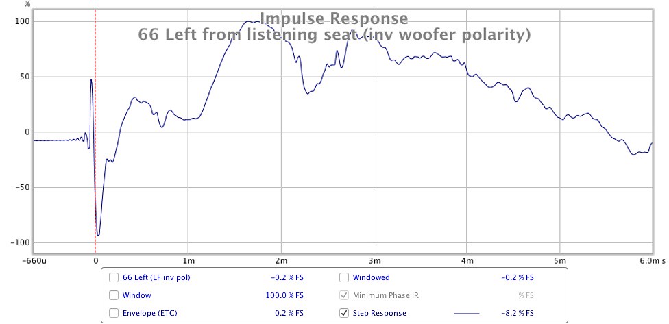 [
[
This clears a few things up, Alan, thank you! It’s great to finally understand what is contributing to each part of the IR.
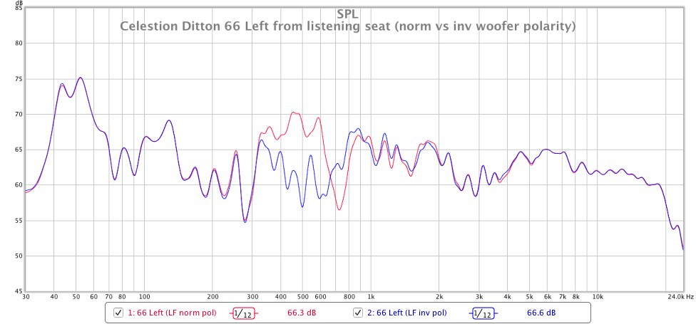
I therefore went ahead and reversed the polarity of the other woofer and have been living with the speakers as an ‘inverted LF’ pair for just over a week now and it has been nothing short of a revelation. One downside I‘ve noticed is, subjectively, the change in vertical off-axis response has become more marked (e.g. when you stand up and walk towards the speaker the LF/MF balance changes more dramatically than before and the effect can be a little odd). However, when listening in the sweet spot, the presentation ‘locks’ into place and is eerily realistic.
The tweeters in my 2015 66s were very crudely selected at the time by ear using 5KHz-20kHz band filtered pink noise (i.e. the first two units I found that produced a similar output volume were the units I chose to install!). The tweeters in my 2018 66s were frequency swept and selected based on closest-matching amplitude responses. Unfortunately however, I did not realise the importance of taking the measurements of the tweeter actually mounted in the cabinet, which is perhaps why they turned out to be not quite so close a match as my baffle-less measurements initially suggested.
It is my intention to eventually experiment with the best measuring HF2000 units I identified a few weeks ago during my 2019 66 refurbishment, to see if I can obtain closer matches and smoother responses, especially in my 2015 66s which do sound rather ‘zesty’ up top!
Looking back at the individual circuit responses in #1214 I wonder if Celestion should have moved the LF roll-off earlier than 500Hz whilst keeping the MF roll-off at 500-600Hz, to intentionally create a dip in the response and reduce the ‘warmth’ / ‘bloat’ that is audible at these frequencies? When wired as standard, my ears tell me the woofer is not rolling off early enough. I guess that rolling the woofer off earlier (or adding a filter to the crossover to reduce its output from 300-500Hz) would likely have created more problems than it solved?!
As the other graphs I posted in #1255 were taken nearfield, I suspect the impulse responses I posted in #1255 must also be nearfield. Here are the farfield IRs:in #1211 on page 122 , you noted that the Impulse Response for the 66 was:
Farfield , on-axis with MF ,
thus I am presuming you have Farfield and on-axis MF for your more recent #1255 Impulse Responses ,
and it seems that they are ...
The first and recent IRs for the standard Celestion polarity connections -{ and ignoring the small ripples before the first high magnitude Positive peak }-
show Mid-dome signal arriving first , followed very closely by Tweeter delayed by a fraction of a millisecond as result of slightly further distance to mid-dome.
Mid-dome is the high Positive peak but it is narrow because the very soon arrival of tweeter signal in Reverse Polarity pushed the IR down into Negative.
Tweeter response finishes first , and the slope up is the recovery of the remainder of the Mid-dome response + the Positive Polarity of the Woofer response which arrives after the two higher drivers as woofer is further from microphone.
The IR is next very soon pushed to Negative by the arrival of the ABR signal which is Reverse Polarity to the woofer.
In comparison , your second IR plot with the reversed polarity woofer shows less recovery to Positive with the mid-dome as the Negative connected woofer pulls the Positive connected mid-dome down a little.
Next arrival is the large Positive from the ABR - Positive now because as the woofer has been reversed the ABR is thereby double-reversed into Positive.
The remaining later signal is a mixture of mid-dome + woofer + ABR in both plots , and it finished differently as result of the different Polarities' connections for each.
This clears a few things up, Alan, thank you! It’s great to finally understand what is contributing to each part of the IR.
It really is quite remarkable what an audible difference this has made to the perceived ‘clarity’ and ‘speed’ of the presentation. The differences become even more audible and measurable at farfield distance:The Phase Response plots are more complicated , but first: see the +180 degrees and -180 degrees Vertical Axis.
Complete Phase Rotation is 360 degrees in Total.
That measurement device does not directly show 360 degrees - it shows the difference from +180 down to -180 , that is the 360 degrees.
Each Vertical line is the device showing the continuous Phase Shift , as having used up all its degrees height scale it stops at the bottom of the vertical scale and starts again at the top of the vertical scale.
Its initial start , and subsequent vertical changeover frequencies , are decided by the Polarity differences ,
from lowest frequency ABR response , then Woofer , then Mid-dome.
Note that the Mid-dome to Tweeter phase change is the same in both plots.
Comparing the Frequency Amplitude response plots , 300 Hz to 900 Hz shows the interactions between Woofer and Mid-dome for both polarity options , because both drivers contribute significantly on both sides of the nominal crossover point.
The 700 Hz to 750 Hz portion of all those plots shows the Phase Cancellation result of later arriving signal from woofer pulling down the mid-dome response ,
and that is changed when the Polarity of the woofer is reversed.
Also , when the polarity of the woofer is reversed the woofer's contribution to the midrange response over the entire 300 Hz to 900 Hz band causes some other - smaller - changes as result of the relative signal arrival times and phase differences to those after woofer polarity change.
I therefore went ahead and reversed the polarity of the other woofer and have been living with the speakers as an ‘inverted LF’ pair for just over a week now and it has been nothing short of a revelation. One downside I‘ve noticed is, subjectively, the change in vertical off-axis response has become more marked (e.g. when you stand up and walk towards the speaker the LF/MF balance changes more dramatically than before and the effect can be a little odd). However, when listening in the sweet spot, the presentation ‘locks’ into place and is eerily realistic.
Apologies for any confusion. I did not remove the tweeters from either my 2018 or 2015 66s to include in the measurement process of my latest 2019 refurbishment so I have no record of how they measure when all other variables are held constant.In #1255 I note the really good frequency amplitude result of mid-range to tweeter from about 4.5 kHz to about 18 kHz for 66R ,
and my guess is that includes your HF9 tweeter ?
I do not recognize which tweeter is in 66L , but that may be result of a slightly different Vertical measurement Axis here to the one you used for your earlier tweeters' HF comparisons ... ?
... and it has a top octave response that my hearing would not like with various music styles ,
and as you earlier stated you can hear Tones to 13 kHz , but detect differences higher in frequency. I am surprised that you have used that HF for your Pairing because from 13kHz upwards both tweeters measure significantly differently !
In #1253 plots I like the 2018 Red plotted midrange to tweeter measured response ,
but not the 2015 Blue at the 3 kHz to 4 kHz crossover overlap region , and also not in the 7 kHz to 15 kHz of treble ,
and Outch ! - I'd hear that broad peak from just above 7 kHz to almost 12 kHz ...
Which HF numbered tweeter is that one ?
{ Yes , I do know that each tweeter's response changes in part when combined with a different mid-dome sample.}
The tweeters in my 2015 66s were very crudely selected at the time by ear using 5KHz-20kHz band filtered pink noise (i.e. the first two units I found that produced a similar output volume were the units I chose to install!). The tweeters in my 2018 66s were frequency swept and selected based on closest-matching amplitude responses. Unfortunately however, I did not realise the importance of taking the measurements of the tweeter actually mounted in the cabinet, which is perhaps why they turned out to be not quite so close a match as my baffle-less measurements initially suggested.
It is my intention to eventually experiment with the best measuring HF2000 units I identified a few weeks ago during my 2019 66 refurbishment, to see if I can obtain closer matches and smoother responses, especially in my 2015 66s which do sound rather ‘zesty’ up top!
This is good to know. Before seeing any of the graphs and reading your above explanation, my original expectation was for the higher crossover frequency of the 24uf to produce less overlap in the response between the MF and LF drivers, thereby producing a slightly ‘thinner’ or ‘leaner’ sound at the crossover frequencies. However it is now evident that factors such as impedance curves and phase shifts makes things a lot more complex than this!In 2015 T1600 versus 2018 T2169 the higher output of 2015 around 600 Hz will be the result of the 30uF capacitor passing more midrange than the 24uF in 2018 ,
and the differences between 300 Hz to about 540 Hz will likely be result of different Impedance magnitudes of the mid-domes in each interacting thereby differently to the roll-off action of the Impedance combination of the mid-section crossover low-mids' rolloff ,
plus any differences between the relative Impedances of the two different Woofers in that frequency band interacting with the woofer section roll-off of the crossover.
{ It is possible for two Woofers to have almost identical measured Amplitude Responses when measured with no crossover in circuit ,
but if each woofer has a different magnitude of electrical Impedance each woofer will interact differently with the same sample of crossover network and thereby have altered Amplitude magnitudes over that portion of their bandwidth.}
For the same reasons as above the T1600 woofer can measure and sound different to the T2169 woofer in the 2018 midrange and crossover combination ,
that is both as result of Impedance Magnitude differences and as result of the Phase differences through the crossover bandwidth because 24uF causes more Phase Shift than 30uF through that overlap bandwidth of mid-dome + woofer.
Looking back at the individual circuit responses in #1214 I wonder if Celestion should have moved the LF roll-off earlier than 500Hz whilst keeping the MF roll-off at 500-600Hz, to intentionally create a dip in the response and reduce the ‘warmth’ / ‘bloat’ that is audible at these frequencies? When wired as standard, my ears tell me the woofer is not rolling off early enough. I guess that rolling the woofer off earlier (or adding a filter to the crossover to reduce its output from 300-500Hz) would likely have created more problems than it solved?!
Good idea, thanks!ISomething I forgot to include in an earlier Post:
As you bought Alligator/Crocodile clips to use to attach wires to drivers for quick change-overs during driver comparisons ,
I recommend that you buy two more Alligator/Crocodile clips , and attach one to each of two short pieces of a suitable thickness of Wire that will insert and hold securely in the slots of your Multimeter for Capacitance measuring.
The Resistance of the wire will be negligible , and if you keep each wire separated some distance from the other neither will cause any effect on the actual Capacitance.
{ Capacitance is relevant to Distance between the conducting plates inside the capacitor and the Distance between whatever conductors that the capacitor is connected to externally.}
Use as above to measure the capacitances of your old short-cut leads capacitors.
Last edited:
Hi starbender ,
I remember when 442 , 551 , 662 models were released which was quite a number of years after the two versions of 44 and 66 -{ there was no previous 55 model }- ,
and 332 was soon after 442.
551 and 442 were fairly well received by the Hi-Fi Press , but less so for 662 , and I do not remember the response to 332.
442 and 662 are more than a little different to 44 and 66 , thus likely 332 is audibly noticeably different to original 33 ,
but as all were 3-way it is likely the Tweeters were connected in Negative Polarity versus Mid-drivers in Positive Polarity , as with the previous series.
Celestion used to supply crossover schematics to Owners who wanted to re-condition their 44s and 66s , thus I suppose Celestion would have supplied schematics for 332 and 442 , etc ...
but now that Celestion is owned by the Asian Gold Peak Industries I do not know if they will supply schematics.
I suggest you email to the British Celestion address , and not to the International nor Asian , and ask for schematics , and offer to pay for cost of finding and sending -{ as that demonstrates Respect and Goodwill }- and wait to find if any response.
If your loudspeakers have Serial Numbers printed on the backs of the cabinets then quote those in your query as that indicates that you are a Celestion Owner , and then there would be greater likelihood of a positive reply.
Also , post a Celestion 332 and 442 Thread in diyAudio and ask there ,
and if Celestion later send schematics , then post those in your thread because that helps other Owners , plus may cause some interesting discussion about re-conditioning -{ like the huge amount in this 66 thread ! }.
--- --- ---
Thanks for your reply. I really like the sound signature of 332s. But i'm not sure about crossover and driver polarities. I sent an email to celestion years ago. Never received a reply. I have several three ways. All of them have mid or tweeter drivers connected reverse polarity. When I receive this 332s, previous owner already messed up with it pretty bad. I'll send another mail to british celestion and beg for schematics and wait. If i get response, I'll share details.
Sb.
- Home
- Loudspeakers
- Multi-Way
- Celestion 66 needs mid-range