Cyberpit-san
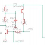
nice, here is an example of turn-on mute. the PNP emitter net is connected to the input voltage before the regulator. upon connection of the supply, the PNP -NPN pair acts as a triac and latches on, until the line MUTEDRIVE is pulled low.
the mutedrive net can be driven by the MPx port, when programmed as a timer delay when the DSP starts executing. monitoring the voltage across the regulator could also warn for turn-off and trigger the mute again.
for example by monitoring a voltage generated by a pnp transistor across the regulator and converted by the AUX adc..
Attachments
Member
Joined 2018
New Muting Tr. Driver Circuit
Hi basreflex-San,
Thanks a lot.
Well, there are many ways to detect the power issues.
My DSP code is not so reliable, so I would go with HW solution rather than SW.
Additionally reason is keeping free limited ADAU1701HW(MPxx) resources .
Here is my current muting driver circuit.
Hi basreflex-San,
Thanks a lot.
Well, there are many ways to detect the power issues.
My DSP code is not so reliable, so I would go with HW solution rather than SW.
Additionally reason is keeping free limited ADAU1701HW(MPxx) resources .
Here is my current muting driver circuit.
Attachments
Member
Joined 2018
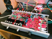
2way Amp Installation
Hi all,
Current Status is still in evaluation...
DIY DSP PROCESSOR PROJECT PAGE
HILO
Hi all,
Current Status is still in evaluation...
DIY DSP PROCESSOR PROJECT PAGE
HILO
Attachments
Last edited:
Member
Joined 2018
That's recycled junk chassis.nice chassis,where did you buy that ?

Originally used in MP3 paging player. Not in sale now...
Member
Joined 2018
192kHz Sampling Crossover Project Evaluated
Hi there?
I have tested 192kHz Sampling 2way Crossover project with my ADAU1701 board.
It works fine, Analog I/O but it's a HI-Res Audio Crossover.
DIY DSP PROCESSOR PROJECT PAGE
(fs=48kHz) (fs=192kHz)
Hi there?
I have tested 192kHz Sampling 2way Crossover project with my ADAU1701 board.
It works fine, Analog I/O but it's a HI-Res Audio Crossover.
DIY DSP PROCESSOR PROJECT PAGE
(fs=48kHz)
(fs=192kHz)
Last edited:
Hello,
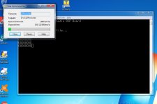
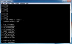
I have FreeDSP classic with arduino nano programmer.
When I am uploading HEX file to eprom do I need to power FreeDSP board by its 12V too ?
Thank you,
Emil
I have FreeDSP classic with arduino nano programmer.
When I am uploading HEX file to eprom do I need to power FreeDSP board by its 12V too ?
Thank you,
Emil
Member
Joined 2018
Hi emilvv-San,
Yes, EEPROM power pin8 should be stable during the data write operation.When I am uploading HEX file to eprom do I need to power FreeDSP board by its 12V too ?
Stereo imaging
I am using a single FreeDSP board for one audio channel (left) in an active speaker.
Another FreeDSP board is fitted in the other active speaker and is serving the other (right) audio channel.
The imaging in a stereo setup is (almost) totally lost.
Here's my question:
which clock(s) do i have to synchronise? Is it only the master clock which is available on the expension header? Or do I also need other clocks to synchronise? likewise LRCLK, BCLK..
Member
Joined 2018
Hi Piersma-San,
So you need to add some delays into the Left-channel.
In case of your I2S bus signal distributed to both channel (in parallel), I guess the received data will be latched into the DSP synchronized with the LRCK transition. Remember to set the I2S ports should set to the Slave(Follower)-mode.
If your Right-channel sound via Left-channel DSP, It will takes some time to receiving I2S, DSP data handling and sending I2S in the serializer. As a result of this, the Right-channel sound will be delayed some.Another FreeDSP board is fitted in the other active speaker and is serving the other (right) audio channel.
So you need to add some delays into the Left-channel.
In case of your I2S bus signal distributed to both channel (in parallel), I guess the received data will be latched into the DSP synchronized with the LRCK transition. Remember to set the I2S ports should set to the Slave(Follower)-mode.
Extending I2S
Hi Cyberpit,
I think your proposed method would work but
I looked into the issues of propagating I2S over serveral meters and came to the conclusion a buffer would defenitely be needed.
For now I will leave the idea of extending the I2S signals.
Thanks for your support !
Hi Cyberpit,
I think your proposed method would work but
I looked into the issues of propagating I2S over serveral meters and came to the conclusion a buffer would defenitely be needed.
For now I will leave the idea of extending the I2S signals.
Thanks for your support !
Member
Joined 2018
Hi Piersma-San,
DS90LV047ATM(LVDS Driver)
DS90LV048ATM(LVDS Receiver)
And using with quad twisted-pair cable (such as CAT5 or HDMI-Cable...) will be fit for your needs.
Well, It's difficult to extend MCLK and I2S signal path with copper cables.I looked into the issues of propagating I2S over serveral meters and came to the conclusion a buffer would defenitely be needed.
For now I will leave the idea of extending the I2S signals.
DS90LV047ATM(LVDS Driver)
DS90LV048ATM(LVDS Receiver)
And using with quad twisted-pair cable (such as CAT5 or HDMI-Cable...) will be fit for your needs.
external DAC PCM5102A
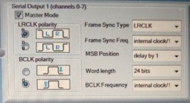
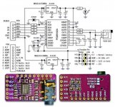
Decided to extend the FreeDSP with an external DAC. Advantage is the increased voltage output capabilities and dynamic range of the PCM5102A.
Note that you have to change the polarity of the I2S bitclock.
The bitclock polarity is set from negative to positive.
Decided to extend the FreeDSP with an external DAC. Advantage is the increased voltage output capabilities and dynamic range of the PCM5102A.
Note that you have to change the polarity of the I2S bitclock.
The bitclock polarity is set from negative to positive.
Attachments
Member
Joined 2018
Hi Piersma-San,
I agree with you, It's an important point using with embedded DAC with external DACs...
FreeDSP Classic SMD A/B and the FreeDSP Classic SMD A/B plus II has 2V phase corrected outputs.
They don't need to care those things.😀
I agree with you, It's an important point using with embedded DAC with external DACs...
Well, most of ADAU1701 based FreeDSP board has phase inverted 0.9V output except my designs.Note that you have to change the polarity of the I2S bitclock.
The bitclock polarity is set from negative to positive.
FreeDSP Classic SMD A/B and the FreeDSP Classic SMD A/B plus II has 2V phase corrected outputs.
They don't need to care those things.😀
Last edited:
- Home
- Source & Line
- Digital Line Level
- freeDSP - an open source 2-in 4-out digital crossover board