If and when you find such posts, kindly mention their index numbers here so that future readers can discover them more easily.
Besides this searching through thread and its much weightier predecessor, Official M2 schematic , you could also look at the M2 Manual on First Watt's website. It has measurement data on pages 5, 6, and 10. Jim/6L6 put a link to the manual in post #2 of this thread, but honestly it's a little faster to simply google search for First Watt M2 Manual.
_
Last edited:
If and when you find such posts, kindly mention their index numbers here so that future readers can discover them more easily.
Besides this searching through thread and its much weightier predecessor, Official M2 schematic , you could also look at the M2 Manual on First Watt's website. It has measurement data on pages 5, 6, and 10. Jim/6L6 put a link to the manual in post #2 of this thread, but honestly it's a little faster to simply google search for First Watt M2 Manual.
_
Thanks Mark. I had already downloaded and read the manual you mentioned. I was specifically wondering if anyone here who has built the M2x kit actually tested what they built and compared their test results with the published specifications claimed in the M2 manual?
These are the results I measured after a repair / rebuild of a friend's M2x kit which uses a 360VA toroidal mains transformer.
Cheers,
Alan
Attachments
Dang! How am I supposed to get any work done while this wonderful amp is playing music??
* ‘work’ meaning the ordering of parts to build the next couple sets of IPS modules, probably SMD Tucson & Mtn View.
* ‘work’ meaning the ordering of parts to build the next couple sets of IPS modules, probably SMD Tucson & Mtn View.
M2 is a three stage amplifier with no global feedback. Stages 1 and 3 are unity gain buffers. It's not a complete shock that the sound, and the measurements, are mostly determined by stage 2. The Edcor transformer.
There was a member here on this thread a few months ago, who was running his own comprehensive battery of lab tests, to design his own RC network that loads the Edcor transformer's secondary. Replacing R5+C1 in the Official M2 Schematic. If I remember correctly he found the white papers on Jensen Transformers' website very helpful in creating lab tests and interpreting results. Jensen advocates optimizing the network in the time domain, shooting for a Bessel response (zeta = 0.866). But how does that sound compared to the stock M2 values?
There was a member here on this thread a few months ago, who was running his own comprehensive battery of lab tests, to design his own RC network that loads the Edcor transformer's secondary. Replacing R5+C1 in the Official M2 Schematic. If I remember correctly he found the white papers on Jensen Transformers' website very helpful in creating lab tests and interpreting results. Jensen advocates optimizing the network in the time domain, shooting for a Bessel response (zeta = 0.866). But how does that sound compared to the stock M2 values?
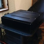
It has been a pleasure to listen to the new M2x for the last couple days. As my last post indicated, it has that wonderfully engaging quality that tends to thoroughly distract one from other thoughts or tasks while the music is playing. It seems to have enjoyed a relatively brief 'break-in' period compared to the ACA builds I have done. It did mellow out a bit, but has remained stable in timbre, dynamics and presentation after about four hours vs. about 20 for the ACA. This is the fist big Papa amp that I have built and had a chance to listen to for a while in my system. It's been a pleasure to have the extra headroom for when I want just a little 'more.'
I am also happy to report that it is nearly silent. I can only hear a very faint 60/120 Hz hum when my ear is next to the speaker grill cloth. No noise is detectable from the listening position. I may try rotating the transformer case a few degrees just to see if that changes anything. Or not. The minute amount of hum is really a non-issue.
Since I have become accustomed to the sound of my various ACA builds, all of which are either dual-mono or separate monoblocks, the character of the M2x sound stage with its single power supply is noticeably more concentrated toward the center. It still does a good job of making the speakers 'disappear', but doesn't expand beyond the speaker centerlines. Top to bottom and front to back imaging seems slightly restricted as well. At the beginning of the build, I had considered using a pair of 200VA transformers in steel cases. Two capacitor boards would have just fit, if I had used monolithic bridge rectifiers instead of discrete diodes. I chose instead to go with the a single supply with the standard amount of overkill, a 400VA transformer and 22000 uF capacitors. The discrete diodes did buy me about 1.5 Volts on the power rails, which I like to have as a power reserve. As things stand, switching to a dual-mono supply would be a major amount of rework, and probably more trouble than it is worth. I have a couple other ideas in mind to improve channel separation.
As with the other amps I've been listening to recently, my system remains as follows:
CD player - Naim CDX2 w/ diy XPS DR power supply (using Sigma 22 regulators)
Preamp - Naim NAC 82 w/ diy dual HiCap DR power supply (using Sigma 11 regulators)
Speakers - Vandersteen 2C
Attachments

Last edited:
Please keep us posted on the 'couple of other ideas'. (I have a few ACA enhancement parts on order already, but haven't started the M2x yet.)
It has been a pleasure to listen to the new M2x for the last couple days. As my last post indicated, it has that wonderfully engaging quality that tends to thoroughly distract one from other thoughts or tasks while the music is playing. It seems to have enjoyed a relatively brief 'break-in' period compared to the ACA builds I have done. It did mellow out a bit, but has remained stable in timbre, dynamics and presentation after about four hours vs. about 20 for the ACA. This is the fist big Papa amp that I have built and had a chance to listen to for a while in my system. It's been a pleasure to have the extra headroom for when I want just a little 'more.'
I am also happy to report that it is nearly silent. I can only hear a very faint 60/120 Hz hum when my ear is next to the speaker grill cloth. No noise is detectable from the listening position. I may try rotating the transformer case a few degrees just to see if that changes anything. Or not. The minute amount of hum is really a non-issue.
Since I have become accustomed to the sound of my various ACA builds, all of which are either dual-mono or separate monoblocks, the character of the M2x sound stage with its single power supply is noticeably more concentrated toward the center. It still does a good job of making the speakers 'disappear', but doesn't expand beyond the speaker centerlines. Top to bottom and front to back imaging seems slightly restricted as well. At the beginning of the build, I had considered using a pair of 200VA transformers in steel cases. Two capacitor boards would have just fit, if I had used monolithic bridge rectifiers instead of discrete diodes. I chose instead to go with the a single supply with the standard amount of overkill, a 400VA transformer and 22000 uF capacitors. The discrete diodes did buy me about 1.5 Volts on the power rails, which I like to have as a power reserve. As things stand, switching to a dual-mono supply would be a major amount of rework, and probably more trouble than it is worth. I have a couple other ideas in mind to improve channel separation.
As with the other amps I've been listening to recently, my system remains as follows:
CD player - Naim CDX2 w/ diy XPS DR power supply (using Sigma 22 regulators)
Preamp - Naim NAC 82 w/ diy dual HiCap DR power supply (using Sigma 11 regulators)
Speakers - Vandersteen 2C
Hi,
Did you ever compare your "FirstWatt" amps to a Naim ?
There were two stages of options that I had in mind. The first involved adding local capacitance to each channel board. The second, more drastic stage, was to add capacitance multipliers local to each power rail. See the K multiplier for an example.Please keep us posted on the 'couple of other ideas'. (I have a few ACA enhancement parts on order already, but haven't started the M2x yet.)
Fortunately the solution proved to be quite straightforward, as I had already acquired some special parts in anticipation. Following another recommendation by the Wiley Zen Mod, I had a set of motor run capacitors on hand. These did the trick. The soundstage has opened up quite nicely, as has the top end. Transient attacks of percussion instruments have also been improved. Quite frankly, this is what I had hoped a big Papa amp would sound like. Musically involving, detailed and non-fatiguing.
These particular caps were 40 uF, 450V oil-filled polypropelene. They are sourced in the US and carry the CBB60 and MKP markings. Search for "CBB60 motor run capacitor." Make sure they are run and not start caps.
The amp is now ready to use as a platform for evaluating the various IPS boards. I will order parts for the Tuscon and Mtn View next.
Attachments
You might want to experiment with where you connect the two leads of your new supply bypass capacitors.
Maybe you've got a tightly twisted pair of wires that connect between the amp board and the positive output of the PSU, where the two twisted wires carry VPOS and GND. If so, connecting the new bypass cap right at the VPOS and GND FastOn spade connectors on the amp board, might be worth trying. You also might have another tightly twisted pair of wires that connect between the amp board and the negative output of the PSU. Those two twisted wires carry VNEG and GND. Their FastOn spade connectors on the amp board, might be a good place to try connecting the other bypass cap.
OR, perhaps right at the drain leg of the output MOSFETs (where MOSFET connects to supply) would be a better place to connect the VPOS end and the VNEG end of the bypass caps.
You will probably be able to dream up another few possibilities to try.
Yeah, I did that last one 😉You might want to experiment with where you connect the two leads of your new supply bypass capacitors.
You will probably be able to dream up another few possibilities to try.
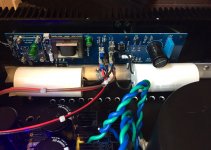
I made a direct ground connection from my PSU board to the speaker negative binding posts. With that in place, the M2x channel boards only use ground as a reference for the VAS, which is the Edcor autoformer. I routed VPOS and VNEG from the PSU to the channel board without twisting in a ground wire. The channel output is routed alongside the ground instead. The last two pictures I posted show how this was done.
With two open GND spade lugs available, I used those for the local motor run caps. The VPOS and VNEG capacitor connections were made through piggyback spade connectors. Very simple and easily reversible if it didn't work the way I hoped.
Yes, I have an older modified "Olive" chassis NAP 250, as well as a more recent unmodified NAP 150 to use whenever I feel like listening to an all-Naim system. I also use dedicated Naim NACA5 speaker cables for the Naim amps. The other amps are run through a pair of Audioquest Bedrock bi-wired cables.Hi,
Did you ever compare your "FirstWatt" amps to a Naim ?
The NAP 250 was one of my earlier modification projects. I added local 470 uF capacitors to the internal power rails of the regulator boards. This made a fairly dramatic improvement to the older PSU which has a single toroid and one pair of reservoir caps that are shared between both channels. I also removed the power limiting circuit from the amplifier boards, as the regulators already take care of power limiting. That helped with overall transparency.
It has been a while since I have made a comparison between the 250 and the various N Pass designs. Need to try that again sometime.
Received my M2X back from Alan Rutlidge today after he fixed up my mistakes and poor implementation. Liking it already, bass extension is very good and snare drum snap is awesome.
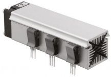
If anyone is considering adding a fan to their M2x for additional cooling, the thread linked below might offer an idea or two. Of course you could mount the fan inside the chassis or outside the chassis; totally your call. You could have one fan or several fans, again your decision. You could even go wild and build a heatsink "tunnel" like the attached picture. The Pass A-20 amplifier project had a similar contrivance.
You can place the thermal sensor wherever you wish; it's at the end of a cable and you can relocate it easily. Monitoring heatsink temperature, bottom-of-chassis temperature, air temperature near the front, air temperature near the rear, anything you choose.
Remember that M2x is a class A amp and its power dissipation is relatively constant, whether it's sitting idle with no input, or playing loud. So the amount of heat to be removed is relatively constant, and the fan airflow required to remove this heat is relatively constant. So the fan will run at a relatively constant speed on a class A amp like M2x. It won't slow down when the music gets quiet. On the other hand, it will take the fan a loooong time after power-on to gradually creep up to its final fan speed. Because it takes a looooong time for M2x itself to gradually creep up to its final equilibrium temperature. There is a lot of thermal mass to warm, and this takes time. The fan will be slower and quieter at turn-on, than it will be 2 hours after turn-on.
Fan inside audio chassis: variable speed, temperature controlled, analog. No PWM.
_
Attachments
Is there a "run in" period? because if there is this amp is going to be monster, it is awesome at only 5 or 6 hours run time.
Hi batty, then on top of that you have the 5 or six different daughter boards to try with the M2X - all are different, but you probably need to listen to each one for a month or so, before swapping to the next. All part of the fun.
Then there are a lot of good preamps to mate with it as well around here. BA3, Korg Nu Tube, Wayne's BA2018 linestage to name a few. Then their sound is influenced by how good a regulated PSU you can choose.
So many combinations to arrive at your ultimate sound choice.
Then there are a lot of good preamps to mate with it as well around here. BA3, Korg Nu Tube, Wayne's BA2018 linestage to name a few. Then their sound is influenced by how good a regulated PSU you can choose.
So many combinations to arrive at your ultimate sound choice.
I fully agree with gary s,
I am listening a lot to my M2X and the NUTUBE - Preamp at the moment.
In the M2X switching between the inputboards, at the Nutube playing with
the adjustment of positive/negative 2nd harmonic, changing preamps,....
I don't have that much time at the moment!
But it's all about beautiful music coming out of this soundmachines.
I don't care that much about measurements.
Greets
Dirk
- Home
- Amplifiers
- Pass Labs
- The diyAudio First Watt M2x