lm1875 transformer
I was just reading the start of this thread and went looking for a suitable transformer based on Daniels recommendation of 36va 18v ct and found a nice cheap one, the Triad Magnetics F36-1000 36VA; Sec:Ser 1.0A; Par 2.0A; Pri:115/230V; Sec:Ser 36VCT; Par 18V; PC. I just ordered it from Arrow.com for $11.68 with free overnight shipping.. we'll see if it's too good to be true or not but this transformer seems cheap from all vendors, the free shipping helps.
https://www.arrow.com/en/products/f36-1000/triad-magnetics
I know a lot of us newbs have trouble finding things, especially reasonably priced transformers. It is a PC mount type so a bracket will be needed (or glue) but it looks like it'll work. I'm using those cheap ebay lm1875 mono board kits and rectifier board. Any thoughts on this one Daniel?
Those transformers are good for LM1875 monoblocks. The transformer's 2 amp limitation is a good match for those ebay chips, which probably aren't actually LM1875. Power boards for monoblocks can be made with 4x schottky, 4x 2200uF, quite simply.I was just reading the start of this thread and went looking for a suitable transformer based on Daniels recommendation of 36va 18v ct and found a nice cheap one, the Triad Magnetics F36-1000 36VA; Sec:Ser 1.0A; Par 2.0A; Pri:115/230V; Sec:Ser 36VCT; Par 18V; PC. I just ordered it from Arrow.com for $11.68 with free overnight shipping.. we'll see if it's too good to be true or not but this transformer seems cheap from all vendors, the free shipping helps.
https://www.arrow.com/en/products/f36-1000/triad-magnetics
I know a lot of us newbs have trouble finding things, especially reasonably priced transformers. It is a PC mount type so a bracket will be needed (or glue) but it looks like it'll work. I'm using those cheap ebay lm1875 mono board kits and rectifier board. Any thoughts on this one Daniel?
The board has a fascinating voicing arranged. The little 100u on power tend toward sharp but clear upper end. And they've swamped the sharpness with heavy bass distortion, by not allowing the amplifier to amplify bass accurately. It makes "warm bass" sound.
RC Low Pass Filter Calculator
1k, 4u7. See chart. Curve ends up IN the audio band. All 3 of those caps are too small.
I think that the board's voicing isn't going to work right, because they did it backwards. Even lots of blurry bass probably can't mask the extra sharpness.
I'd replace the 100u power caps with one of these options:
Pair 220u where the power caps go and another pair 220u forced into the -v,g,+v pads (they'll sort of fit). OR, just a pair 470u of excellent quality.
The difference is, 2 pair smaller caps and you're not the capacitor quality control department, or a simple pair larger caps and you find the good quality caps for it.
As for the 1k+47u RC, use the rc calculator and aim for a pitch anywhere lower than 1hz.
The input cap? 10uF isn't quite right (lets in some frequencies too low to hear but will worsen clipping). It probably needs 2.2u size for input. 1u also works if medium to small speakers.
If you've got 2 boards, that's great--try one stock and mod the other so you can compare.
Last edited:
Thanks for the info 🙂
I have 50-63v 470uF Nichicon muse and Cerafine caps so the power caps are no problem. I don't have anything lower than 10uF that I can find at the moment. As for the 1k+47uF, I have no idea what I'd even need to calculate, so I'll probably leave those for now.
By the way, the amp isn't for speaker use, it's to power step-up transformers for electrostatic headphones (Stax energizer boxes) so the loads may well be very different than speakers.
Looks like changing the 1k resistor to a 22k will give me 0.15Hz. Alternatively the 1k with a 220uF will give 0.72Hz. Any preference? Option #2 is easier for me with what I have available.
If you change the resistor value, you will also change the gain. Use anything between 100 and 220uF.
Thanks, Mark.
That settles it, 220uF it is. Definitely a big step up from 47uF!
I apologize for my cluelessness but old dog, new tricks. I'm slowly picking things up though.
Finally, is it Ok to mix 470uF caps with different voltages because I can either put 2x 50v on one board and 2x 63v on the other, or put one of each in both boards so they match. I'm not sure if the voltage rating matters as long as it's sufficient and both have the same capacitance. Both cap types are very good quality.
I use those beautiful green (Muse) ones from Nichicon. It's important to colour coordinate your build.��
Surprisingly good news, Arrow came through with the cheapest price on that transformer and it arrived this morning with free overnight shipping!
Color me impressed, I Think I'll be ordering more from them. I find Mouser and digikey too costly for the small orders I make.
Color me impressed, I Think I'll be ordering more from them. I find Mouser and digikey too costly for the small orders I make.
isnotdynamic, you have got Nichicon FZ polarized Electrolytics. These are Black/ Gold with Muse written on it. The green Nichicon ES are np Electrolytic Capacitors.
I've built quite a few LM1875 in different schematics with never the same Components. All I recognized is, an Amp with the cheapest parts can sound as good as one with more expensive Components, if it is built small, with shortest possible Signal Path and clean Layout. I have got 6 LM1875 at the moment in my Speakers and they sound really great. but as the Amps are partly built with different Parts, I deceided to built 6 last Amps with same Components. I think I'll use good, but not expensive Parts as in the Schematic.
I've built quite a few LM1875 in different schematics with never the same Components. All I recognized is, an Amp with the cheapest parts can sound as good as one with more expensive Components, if it is built small, with shortest possible Signal Path and clean Layout. I have got 6 LM1875 at the moment in my Speakers and they sound really great. but as the Amps are partly built with different Parts, I deceided to built 6 last Amps with same Components. I think I'll use good, but not expensive Parts as in the Schematic.
Attachments
Clueless but avid... I can relate 😉
good to know. My kit is now pretty similar to that but still has the 10uF cap. The nearest I have to the 1.5uF listed are gigantic WIMA 1Uf MKP 10 X7 400V-/250~10% Which are almost as big as the amp board, but I'm sure I could get it to fit ;p
good to know. My kit is now pretty similar to that but still has the 10uF cap. The nearest I have to the 1.5uF listed are gigantic WIMA 1Uf MKP 10 X7 400V-/250~10% Which are almost as big as the amp board, but I'm sure I could get it to fit ;p
ok, I know very little about circuits and would love some instruction on the very basics of these things. Here is a stock ebay board which many of us have..

My question is, what bits do what and why? Nothing overly complicated or detailed, just an overview so I can get a better grasp on what people are talking about. All discussions seem to begin with an understanding above these basics. Things like input caps, decoupling caps etc. I'm not really able to follow very well and this board is simple enough that a small guide as to what's what would go a long way to a better understanding.
My question is, what bits do what and why? Nothing overly complicated or detailed, just an overview so I can get a better grasp on what people are talking about. All discussions seem to begin with an understanding above these basics. Things like input caps, decoupling caps etc. I'm not really able to follow very well and this board is simple enough that a small guide as to what's what would go a long way to a better understanding.
Last edited:
You need to read the datasheet first, there are plenty of info there.
ABC of electronics is very nice if you are into electronics, and you will not need a teacher at that level , later , sure, some will explain you stuff .
For your board, get components from reliable sources, put it together , it’s fun!
ABC of electronics is very nice if you are into electronics, and you will not need a teacher at that level , later , sure, some will explain you stuff .
For your board, get components from reliable sources, put it together , it’s fun!
I read the data sheet and read some stuff online but it's all very abstract for my way of thinking. The kinds of things I'm looking to understand has to be related to an actual item like this board which I can then transfer to other similar things.
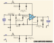
For instance, using the schematic at the top of the page,
Across the input signals there is a 1meg resistor, that's there because....?
After that, there's a 1k resistor in parallel to a 20k resistor that's in series with a 220pF capacitor, this determines...?
The two 220uF caps are the..? caps, there to...? and they work together with the 100nF caps which reduces...?
This is my problem. I don't really understand what each section does or why and I'm too dense to figure it out unless it's pointed out in simple terms. I'll never understand electronics beyond very basic levels but a general grounding of a simple circuit like this will at least give me some idea.
In automotive terms, I guess the equivalent would be something along the lines of...
At the inlet there is an air filter, this prevents dust/dirt entering the engine, next is a carburetor that delivers a fuel and air mixture. The amount is governed by a valve, how open the valve is determines how fast the engine revs. Inside the carb is a small fuel chamber with a float valve whose job is prevent excess fuel entering the fuel delivery valve to avoid flooding. Once the fuel and air is mixed, it flows into the cylinders via timed inlet valves at the top of the cylinder head.. etc
Mechanics are easier for me to understand 😛
Thanks, Mark.
Nice op-amp introduction, unfortunately for me, the bits I'm most interested in are the bits where Dave says "but I won't go into that here" 🙄 I've been racking my brain over the diagram above trying to figure it out, could anyone see if I'm somewhat correct in my guessing here.
The 1.5uF = input noise filtering
The 100uF + resistor = gain level
The 220uF = supply stabilizer
The 220pF = current drain
The nF caps = high frequency filtering (ringing?)
The 1k & 20k resistor pairs = +input and -NFB loop.
The 1meg resistor = keep input impedance high
The 10 and 1 Ohm resistors, no real idea! Short protection? Output impedance?
These are my best guesses based on what seems to make sense to me, for whatever that's worth 🙂
A Complete Guide to Design and Build a Hi-Fi LM3886 Amplifier - Circuit Basics Some of your answers can be found here. If you start at the output of the ic and work towards the input might be easier. Where does the output voltage and the current come from? PSU, capacitors?
Last edited:
Hi everyone,
I'm a newbie for circuit cause I'm working on speaker project. But about software side.
So I already ordered one pcb from internet then solder by instructions. But problem is my preamp is so much strong, the sound is clipping over 60% volume.
Hope someone can help me modify the resistor NFB to adaptive with my preamp.
This is pcb with shemactic
Amplifier PCB for TDA2030/LM1875 - oddWires
Thanks you so much !!!!
Altering the gain by altering the feedback could cause you big problems with stability. Whilst it can be done, it requires addition of other parts and so is not recommended for a beginner.
The simplest and safest solution would be to add a series resistor to the input to the board. 22k would divide the signal by 2 as it would form a divider with the input bias resistor already present.
The simplest and safest solution would be to add a series resistor to the input to the board. 22k would divide the signal by 2 as it would form a divider with the input bias resistor already present.
- Home
- Amplifiers
- Chip Amps
- Beginner's Gainclone, HiFi LM1875, The Amplifier Board