Hello
I have a TSE PCB which I snatched up before George ran out for the re-design and I would like to build a choke-input power supply for it.
I plan on running it with 45s, so my B+ goal is roughly 300V @ 100mA.
I plan on using the 260-0-260 taps of "Universal" Tubelab Edcor power transformer (edcor xpwr131) with a stated secondary DCR of 70 ohms end to end (35 ohms from CT), per a thread here.
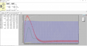
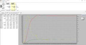
For the PSUD sim:
260VAC = 520pk-pk= 372Vrms. [Edit: 520*.707= (approx) 368Vrms]
I'm dividing the 300V B+ by 90mA ("rounded up" sum of currents to power and preamp tubes through B+) to get the 3.3K Ohm value for R1.
L1 is spec'd for a Hammond 159Q
L2 is spec'd for a Hammond 159S
Soft-start is disengaged for the sim.
PSUD isn't giving me any warnings but I would still appreciate it if somebody more versed in this could check my work.
Thanks in advance.
I have a TSE PCB which I snatched up before George ran out for the re-design and I would like to build a choke-input power supply for it.
I plan on running it with 45s, so my B+ goal is roughly 300V @ 100mA.
I plan on using the 260-0-260 taps of "Universal" Tubelab Edcor power transformer (edcor xpwr131) with a stated secondary DCR of 70 ohms end to end (35 ohms from CT), per a thread here.
For the PSUD sim:
260VAC = 520pk-pk= 372Vrms. [Edit: 520*.707= (approx) 368Vrms]
I'm dividing the 300V B+ by 90mA ("rounded up" sum of currents to power and preamp tubes through B+) to get the 3.3K Ohm value for R1.
L1 is spec'd for a Hammond 159Q
L2 is spec'd for a Hammond 159S
Soft-start is disengaged for the sim.
PSUD isn't giving me any warnings but I would still appreciate it if somebody more versed in this could check my work.
Thanks in advance.
Attachments
Last edited:
First comment, what are you going to bias at? 90ma seems a touch high.
Instead of using a resistive load, I would use a constant current load, and set it for whatever you need.
Instead of using a resistive load, I would use a constant current load, and set it for whatever you need.
Choke input at the filter doesn't need soft start as it is self soft start, given the first inductance in the filter is above certain minimum value for continuous conduction mode.
I made my own inductors from burned 110/220 trafos, recovering the core and bobbin, and winding in it the turns necessary. Then, reassembling the core E and I laminations together, and checking the gap for the lower ripple at output at nominal output current. A short reckoning with window area and wire size gives you how many turns you can place in the bobbin, measuring it with a rule or caliper. Then, with the meal turn length and wire resistance per unit length (available at manufacturer's data sheet or from approximate tables) you can estimate the DCR. If too high, redo from the start. When arrived at a reasonable resistance, the inductance can be estimated from a LCR meter if needed. This is how I make my own inductors. Final adjust would be done in circuit.
I made my own inductors from burned 110/220 trafos, recovering the core and bobbin, and winding in it the turns necessary. Then, reassembling the core E and I laminations together, and checking the gap for the lower ripple at output at nominal output current. A short reckoning with window area and wire size gives you how many turns you can place in the bobbin, measuring it with a rule or caliper. Then, with the meal turn length and wire resistance per unit length (available at manufacturer's data sheet or from approximate tables) you can estimate the DCR. If too high, redo from the start. When arrived at a reasonable resistance, the inductance can be estimated from a LCR meter if needed. This is how I make my own inductors. Final adjust would be done in circuit.
Attachments

Last edited:
First comment, what are you going to bias at? 90ma seems a touch high.
Instead of using a resistive load, I would use a constant current load, and set it for whatever you need.
Other threads regarding the TSE using 45s suggested 90mA as a design goal (roughly 30mA per 45, 15mA per 5842) using 150mA-200mA rated chokes for PS design robustness. I’ll triple-check this though. I’ll also swap R1 with a current source, either 90mA or whatever else may be more realistic.
I made my own inductors from burned 110/220 trafos, recovering the core and bobbin, and winding in it the turns necessary. Then, reassembling the core E and I laminations together, and checking the gap...
I appreciate your comments and think it’s very cool that you’re winding your own chokes using salvaged iron. I have an old tube receiver set aside as it looked promising for parts harvesting. Unfortunately I think winding my own chokes is a bit too ambitious for me right now.
Last edited:
I appreciate your comments and think it’s very cool that you’re winding your own chokes using salvaged iron. I have an old tube receiver set aside as it looked promising for parts harvesting. Unfortunately I think winding my own chokes is a bit too ambitious for me right now.
Perhaps in a short future. A little test will encourage you to make your own chokes, and why not transformers. You don't need too much tools, only a bit of job and idea.
I did purchase some magnet wire a few years back with the intention of winding my own loudspeaker crossover inductors. In fact, I still plan to do so and I appreciate the encouragement.
@randytsuch: it looks like maybe 80mA is a more realistic rough sum of currents. Since I have no intention of running other tubes I might opt for an alternative transformer without the extra windings and B+ capabilities.
@randytsuch: it looks like maybe 80mA is a more realistic rough sum of currents. Since I have no intention of running other tubes I might opt for an alternative transformer without the extra windings and B+ capabilities.
Hello
I have a TSE PCB which I snatched up before George ran out for the re-design and I would like to build a choke-input power supply for it.
I plan on running it with 45s, so my B+ goal is roughly 300V @ 100mA.
I plan on using the 260-0-260 taps of "Universal" Tubelab Edcor power transformer (edcor xpwr131) with a stated secondary DCR of 70 ohms end to end (35 ohms from CT), per a thread here.
For the PSUD sim:
260VAC = 520pk-pk= 372Vrms.
I'm dividing the 300V B+ by 90mA ("rounded up" sum of currents to power and preamp tubes through B+) to get the 3.3K Ohm value for R1.
L1 is spec'd for a Hammond 159Q
L2 is spec'd for a Hammond 159S
Soft-start is disengaged for the sim.
PSUD isn't giving me any warnings but I would still appreciate it if somebody more versed in this could check my work.
Thanks in advance.
Input chokes get hammered really hard. I would spend the extra money and at least get a hammond 193j. That way you have a choke that can stand a bit more abuse and you get the full 10H that your rectifier tube can support.
I would also change the resistor in PSUD to a constant current source. That way you wont have to sit there and double check your math and it makes your life a lot easier.
I might opt for a 220-0-220 power transformer (vs the Tubelab "universal" by Edcor) capable of 150mA or so, though the alternatives aren't really much cheaper.
I also found a 10H, low DCR swinging choke that might be a better choice for L1, which is also along your suggestion.
I will re-sim with these changes, plus a current source set for 80mA.
I caught a math error in my OP.
Thank you everyone and keep the suggestions coming.
I also found a 10H, low DCR swinging choke that might be a better choice for L1, which is also along your suggestion.
I will re-sim with these changes, plus a current source set for 80mA.
I caught a math error in my OP.
Thank you everyone and keep the suggestions coming.
I use an 80ma constant current source as my load, but I would not use any part rated for less than 100ma, and would likely not use a 100ma part, that would not be enough margin for me. I would go for 120ma and up.
Don't confuse design margins and buying parts that will be reliable over the long haul vs how you sim the design.
Your T1 voltage looks high to me. I'm using 345V with 44 ohms in my current sims. I just input what I have running now, a CLCLC with two triad C-14x inductors, and my sim comes out to 285V and I'm actually getting 290V.
Not sure why, but it seems as though my sims can be 5-10v off, but they are ballpark.
Swinging chokes are best when very variable loads must support. With fixed current like class A amplifiers they haven't any advantage.
That's good to know. I discovered PSUD doesn't much care for them either 😉
I'm going to stick to conventional chokes going forward with this power supply.
I'm going to stick to conventional chokes going forward with this power supply.
I suggest to take a reading to one (or more) of the old good text books, like Wallman and Valley, Terman, Gray, Radiotron, etc, they covered the topic extensively. Many of them are available on pfd free in the web.
Believe it or not, I have actual physical copies of those (well, not Gray) but prefer Morgan Jones because I find the engineering-level text impenetrable to a layperson such as myself.
Randy,
What power transformer are you using?
I have the same edcor XPWR131-120. Bought it almost 6 years ago, this project was a long time in the making for me lol.
I even found my edcor to run high, I only have a 1uf cap in at C4 right now, with a 5V4 rectifier tube, although I really don't see much difference when I change rectifier tubes. Guess because I'm using such a small C4, that is really determining my B+.
I am going to try a slightly larger C4 and raise my B+ to maybe 310V or so, but right now busy with taxes.
Randy
If you circumscribe to the chapter about rectifiers and filter ignoring or jumping the theory part you will find interesting information. I strongly suggest to read them, because if you make a simulation, it is difficult to understand what the simulation id telling you. Also, keep in mind that simulation in any way are true results, most of the time they ignore several secondary effects: core saturation, non linearity of the core B-H loops, uncertainty in the gap in the core, stray capacitances/inductances and much more. Theory is a bit complicated, but with a bit of patience, is by far, more interesting that scrolling the display of a cell phone.
I found this a while ago, when I was working on my sims
PSUD newbie: modeling Tubelab SE
I recommended reading the entire thread, but there is an attachment with psud sim files. I used them as a sanity check against my sims.
Randy
PSUD newbie: modeling Tubelab SE
I recommended reading the entire thread, but there is an attachment with psud sim files. I used them as a sanity check against my sims.
Randy
Thank the both of you for the reading suggestions. I’m going to read that thread and also work the math in the choke input power supply section of Ch. 5 of Valve Amplifiers, 4th Ed. by Jones.
After that I’ll do my taxes.
After that I’ll do my taxes.
Thank the both of you for the reading suggestions. I’m going to read that thread and also work the math in the choke input power supply section of Ch. 5 of Valve Amplifiers, 4th Ed. by Jones.
After that I’ll do my taxes.
An FYI, if I plug in my parts into his sim, the voltages come out way low. I have to jack up the T1 voltage to 345 to get it to match about what my TSE does.
I think I was up around 350V with a 47uf cap.
I bought a variac a while ago, its nice to be able to slowly bring up the voltage, and to be able to run at a lower voltage for testing this kind of stuff.
You must be faster at taxes than I am 🙂
Randy, that thread you linked to is actually where I got the 100mA figure:
This is a Tubelab SE. For a pair of 45s, you need to figure 25mA per 45, plus 12mA per 5842, plus about 10mA for each MOSFET...so say 100mA total.
- Home
- More Vendors...
- Tubelab
- Please critique my TSE choke-input PS sim