I think that returning the speaker gnd to PSU gnd directly is of even more importance if bridging is intended or at least it's possibility is given.
But then, how do you twist the speaker leads? Just right down to the amp PCB and let the gnd wire alone run to the PSU?
Best regards!
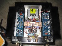
i twist the power rail supply wires, they are not long, 6 inches at the most and #16, the speaker hot wires are segmented, from the HB board to the speaker protection/delay boards, all short runs....where twisting wires will look silly, i would rather not do it..
Attachments
Connecting speaker GND at the PSU does have a (theoretical) increase of THD.
how do you quantify this?
i twist the power rail supply wires, they are not long, 6 inches at the most and #16, the speaker hot wires are segmented, from the HB board to the speaker protection/delay boards, all short runs....where twisting wires will look silly, i would rather not do it..
Ok, the main effect in twisting is reducing the loop inductance of the involved wires. If these are short enough, the benefit of additional twisting indeed can be considered as marginal.
Thanks for these pics! Well done!
Best regards!
how do you quantify this?
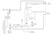
The best point to connect to speaker ground is to the signal ground and then to the star ground. Returning the speaker ground to anywhere else will cause a output error voltage to develop when referenced to the signal ground.
Let us say that this is the perfect layout where the Power, speaker, input/feedback and local decouple grounds connect at F (star-point). Normally F sits somewhere on the amp board. Connecting speaker return to E, as suggested here, adds an error voltage caused by the current between E and H.
Attachments

The best point to connect to speaker ground is to the signal ground and then to the star ground. Returning the speaker ground to anywhere else will cause a output error voltage to develop when referenced to the signal ground.
precisely this is what i am avoiding returning the speaker return wire to the psu cap junction....
How long is a piece of string? Here is the error voltage in red. It will be dependant on the output current, the amount of high-frequency content, the value of the local capacitors to name but a few. If you really want numbers, try simulating the circuit.
Attachments
unless you can put numbers in it, then all is just opinions...
if you propose, you dispose....
if you propose, you dispose....
Does this error voltage exist if the star ground point is made at the power supply? Input stage, output stage and speaker returns all connected separately to the power supply?
The cause of the error voltage is the current flow to and from the local decoupling capacitors. You would also have to connect the local decoupling with a separate wire. making it 4/5 connections per channel.
Here are some numbers
Here are some numbers
Last edited:
way i always understood it, zero reference at the psu ground to the pc board ground are never meant to carry significant current resulting from amplification, just the idle or quiescent operating point currents, and lower this is the better imho...
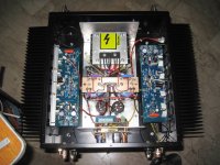
now when the output stage delivered output currents and voltage swings the big currents flow thru the supply rails, thence thru the output trannies out to the speaker hot line, then to the speaker and back to the psu zero volt return point, this is the reason why i put the speaker cold side wire direct to the psu cap junctions...what is hard about this?
now when the output stage delivered output currents and voltage swings the big currents flow thru the supply rails, thence thru the output trannies out to the speaker hot line, then to the speaker and back to the psu zero volt return point, this is the reason why i put the speaker cold side wire direct to the psu cap junctions...what is hard about this?
Because that is not the only thing that is taking place in a class AB amp or the way feedback works. The local decoupling capacitors are supplying current to the output of the amp every time it crosses 0. This is then followed by charging currents to/from the PSU.
Zero reference is wherever you connect the input/feedback ground.
Zero reference is wherever you connect the input/feedback ground.
Thanks again for all that guy's. Just wondering if anyone has upgraded there output stage to a triple EF. There seams to be a lot of advantages to having a triple. No idea why the HD does not employ one.
Thanks again for all that guy's. Just wondering if anyone has upgraded there output stage to a triple EF. There seams to be a lot of advantages to having a triple. No idea why the HD does not employ one.
They have. Look in the Slewmaster thread for the Wolverine.

Wow, right on time. Thanks!
My guess on speaker return is: Same cap that powered the outputs. Looks like 0v center of C13,C17. I absolutely hate doing layout, but during the suffering, I always look for direct-return first (most-direct circuit is correct). So, agreement, of course. This seems excellent for the biggest room in the house.
However, if used for far higher current in a much bigger place, the tone could go a bit forwards when the charge is hindered in that pair of 470u caps... in which case, speaker return to centerpoint of power board is an easy fix. There's a slight cost, but ever so much louder output, requires placid tone for practicality. Some of the audience may be closer to a speaker.
So, howabout a venue size switch, like a DPDT on/on, to change the speaker return point from the technically correct small venue return point, or as-needed to the high-current large venue speaker return point?
This amplifier covers a really broad range of current. So, a switch for venue-size is the best explanation that I can do. Preferably chrome plated?
I'd be a little concerned about groundlift of feedback shunt. Perhaps D1,D2,R4 need a small value bypass capacitor? Can you suggest a likely value?Because that is not the only thing that is taking place in a class AB amp or the way feedback works. The local decoupling capacitors are supplying current to the output of the amp every time it crosses 0...
My guess on speaker return is: Same cap that powered the outputs. Looks like 0v center of C13,C17. I absolutely hate doing layout, but during the suffering, I always look for direct-return first (most-direct circuit is correct). So, agreement, of course. This seems excellent for the biggest room in the house.
However, if used for far higher current in a much bigger place, the tone could go a bit forwards when the charge is hindered in that pair of 470u caps... in which case, speaker return to centerpoint of power board is an easy fix. There's a slight cost, but ever so much louder output, requires placid tone for practicality. Some of the audience may be closer to a speaker.
So, howabout a venue size switch, like a DPDT on/on, to change the speaker return point from the technically correct small venue return point, or as-needed to the high-current large venue speaker return point?
This amplifier covers a really broad range of current. So, a switch for venue-size is the best explanation that I can do. Preferably chrome plated?
Hi,
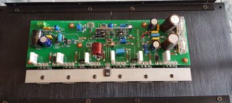
I'm testing 1 channel of the HB amp. Here are the settings of the trimmers.
R7 = 85 ohms
R17 = 250 ohms (midway)
R30 = 550 ohms
All transistors have been installed. I am using the lightbulb approach to limit the current. I am getting readings of 1.2mV on TP1 and TP2 using DMM set to DC mV.
Q1: How many turns of R30 do I have to make to make the mV go up to 25mV? I've tried turning the trimmer 2.5 rounds, but the mV is still hovering around 1.2mv.
Q2: R30 will be around how many ohms to achieve 25mV at TP1 and TP2?
Attachments

- Home
- Amplifiers
- Solid State
- diyAB Amp The "Honey Badger" build thread