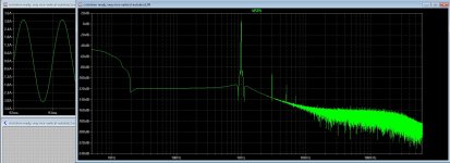
The versions with the current feedback you see clearly the differences with voltage feedback, youn have slightly more distortion but als have a uge bandwidth, current feedback is mine favorite for this, it has not the limitations of voltage feedback, your resisistor network on feedback I do like also, maybe this give a result on the current sources.
The cascode in the Jfet stage is needed as the voltage is higher then max Jfet drain source, so this is always a good idea.
Here the lateral mosfets have 200 mA idle, distortion with almost max swing is -100dB, but because of the current feedback you see down the -100dB more
harmonics, but that is not important as it is so low down the scale.
Idle current has uge impact, see the other -140dB version plot.
regards
with the same output current the Fet is better
I just change Input Cascode for BC546
Input cascode with a bjt do not have much impact.
An inverted version (IRF610) could be better ?
Just sim and see what it does, I think there is no difference, do not use a irf610 this one on 2.4 mA or such wil do not good.
A 2n7000 mosfet does oke if voltage is lower than 60 volts like your 45 volts.
a max 100 mA mosfet is fine with 100 volts D S voltage
2.4mA ? I was talking about replacing the 9610 with 610 and 2SK170 (2sk389) by 2sj109
the current in R18 is really too high 🙂
the current in R18 is really too high 🙂
Last edited:
the current in R18 is really too high 🙂
You need to calculate them, I do now but it is just for simulation and not so important, except when you built it afcourse.
R17 and R18 2.7k or 3.3k will do.
You will find in real world more things who need adjustment.
regards
Update 🙂
- input stage dont need negative supply
- 5mA min on zener
- increase the value of Jfet drain resistance
- RC on output
1) Should I increase the current in JFet?
2) Should I replace the zener for something less noisy ?
3) what do I put in css on input ? Jfet ? bjt with led ?
- input stage dont need negative supply
- 5mA min on zener
- increase the value of Jfet drain resistance
- RC on output
1) Should I increase the current in JFet?
2) Should I replace the zener for something less noisy ?
3) what do I put in css on input ? Jfet ? bjt with led ?
Attachments

Last edited:
Update 🙂
- input stage dont need negative supply
- 5mA min on zener
- increase the value of Jfet drain resistance
- RC on output
1) Should I increase the current in JFet?
2) Should I replace the zener for something less noisy ?
3) what do I put in css on input ? Jfet ? bjt with led ?
That the input stage can work with only a positive supply I did now, however was not shure what the current soruces would do without it, it looks that she work.
The zenerdiodes need a 100n cer cap and a elco of 10 uF, then noise is so low it is below the mosfets itselfs or the Jfet who is higher in noise, but it deep enough from audio you will not hear or notice it, but there are other kind of regulators maybe who are very low noise, You can replace then, but it is shure not needed.
What kind of css is not important, it is for all a high impedance node who do the same, I do not now if sound is impacted by different kinds of transistors, bjt with led will do.
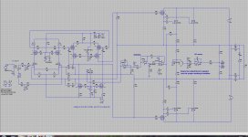
Your long tail pair resistors 5.6k are to high, impedance to high, the mosfet irf9610 has input capacitance who need to be driven, I have use in version with autobias 1.5k and 4 mA bias for jfet, also cascode the vas wil be good for the inputcapacitance be multiplied by irf9610 who is called the miller effect, with a cascode you can prevent this making bandwidth much bigger.
I have included mine auto bias version, even with 50 mA idle I get low distortion because the autobias keeps that stable, I have to go experiment now in real live.
regards
Attachments
On the sim the amp have better distorsion with 5.6k... so the sim is not true
Ok i will add mosfet cascode
Do you know the K4020 amplifier ?
it also has a dynamic bias system in class a
EM_66_p46-52.pdf - Google Drive
Manual_K4020.pdf - Google Drive
Ok i will add mosfet cascode
Do you know the K4020 amplifier ?
it also has a dynamic bias system in class a
EM_66_p46-52.pdf - Google Drive
Manual_K4020.pdf - Google Drive
On the sim the amp have better distorsion with 5.6k... so the sim is not true
Ok i will add mosfet cascode
Do you know the K4020 amplifier ?
it also has a dynamic bias system in class a
Well the point is/was to have servo bias in Class AB, which makes a whole lot of difference.
Your long tail pair resistors 5.6k are to high, impedance to high, the mosfet irf9610 has input capacitance who need to be driven, I have use in version with autobias 1.5k and 4 mA bias for jfet, also cascode the vas wil be good for the inputcapacitance be multiplied by irf9610 who is called the miller effect, with a cascode you can prevent this making bandwidth much bigger.
regards
moschfet use 4.7K on LTP , he may not have paid attention to IRF input cap
https://www.diyaudio.com/forums/sol...-circlotron-power-mosfets-11.html#post3070645
I tried with bjt input, less distortion
Attachments
moschfet use 4.7K on LTP , he may not have paid attention to IRF input cap
https://www.diyaudio.com/forums/sol...-circlotron-power-mosfets-11.html#post3070645
I tried with bjt input, less distortion
Hi Ultimate
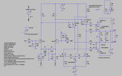
For the problem with the long tail resistors on top of supply rail driving the mosfets, you can optimize these on distortion but keep aware of input capacitance of mosfets special a irf9610 who was 110 pF who de multiplied by gain, for this I use the cascode, you can use on top a small mosfet or even a bjt for use with higher resistances like in long tail pair 5.6k, even the Jfet can be used what is also done in more apliances. The cascode do get rid of the capacitance be multiplied so much what increase the bandwidth.
I will setup one for you.
regards
Thanks kees
What I like with mosfet vas is the fact that the distortion decreases with bias, which is not the case with the bjt
With 2SA1381C i have more distortion with 10 / 15 / 20 than 11mA ...
The transistor for cascode must be matched ? I have 6X 2sj79
What I like with mosfet vas is the fact that the distortion decreases with bias, which is not the case with the bjt
With 2SA1381C i have more distortion with 10 / 15 / 20 than 11mA ...
The transistor for cascode must be matched ? I have 6X 2sj79
Attachments
Last edited:
Thanks kees
What I like with mosfet vas is the fact that the distortion decreases with bias, which is not the case with the bjt
With 2SA1381C i have more distortion with 10 / 15 / 20 than 11mA ...
The transistor for cascode must be matched ? I have 6X 2sj79
because it is a long tail pair, yes, circlotron is a balanced amp zo everything matching is best, but the long tail pair has lowest distortion when matched, but in setup of offset amp because
output vas and mosfets are not matched long tail pair get;s again unbalanced to balance the rest, it is kind of critial, but you can setup a offset pot into the vas itselfs.
Watch the current and voltage through the Jfet.
Different distortions is because of linearity and bias?, find lineair point then.
Last edited:
- Home
- Amplifiers
- Solid State
- allFET circlotron