Is it possible your amp has a resonance and that the startup transient simply causes it to resonate? In this case you have to adjust feedback to reduce the resonance or wait for the resonance to decay.
Is it possible your amp has a resonance and that the startup transient simply causes it to resonate? In this case you have to adjust feedback to reduce the resonance or wait for the resonance to decay.
I have see that when I let it sim for longer time it does decay. Maybe because of the flying capacitor not yet being balanced a kwown problem with flying cap outputs.
But alway nice play with it in ltspice in rhe spare time.
regards
Attachments
Last edited:
Try adding a 'huge' (like 10T or more) resistor in parallel to the flying capacitor.
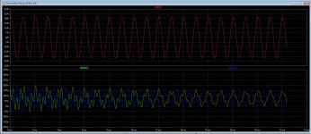
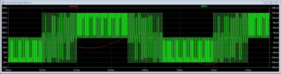
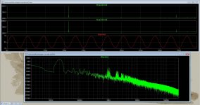
Here I have done something for resolve it.
The first pic you see a strange switching patrone, in pic two you see how it is needed.
what I have done is untick the Start external DC supply voltages at 0 volts and skip initial operating point solution. Then the output is oke like in pc two,
as you see resonances on output or common mode voltage is gone..
I go try the resistor, I do also read that capacitor balance can be cured with a charger, a mosfet can be used who is on for very small time charging the capacitor.
However that is why I am here do not now why LTspice does this fault, or how it change so much in results.
regards
Attachments

Near Gouda (Zevenhuizen) all well.
About the resistor, I think when 'floating' or 'flying' or otherwise capacitors that have no common in/out circuit (like servo's) then introducing a parallel resistor can/will/may solve problems. Just think about it.
The problem is that the capacitors that you are using (in spice) are ideal and have no leakage, some circuits may/will/can 🙂 behave unexpected with 'ideal' capacitors.
Near Gouda (Zevenhuizen) all well.
About the resistor, I think when 'floating' or 'flying' or otherwise capacitors that have no common in/out circuit (like servo's) then introducing a parallel resistor can/will/may solve problems. Just think about it.
The problem is that the capacitors that you are using (in spice) are ideal and have no leakage, some circuits may/will/can 🙂 behave unexpected with 'ideal' capacitors.
I have seen after simulation that indeed the flying capacitors do cause the problems, I can make a precharge circuit, with a voltage source who do set on for one second and then a other puls or inverter who do connect to voltage.
In real live afcause things go faster.
Did see something from internet.
Attachments

Last edited:
LTSPICE question
I am using a model written by Indra1 which is attached.
I have changed the AC voltage source from 1 to 3 and yet the source remains at 1 V p-p when I run the sim.
What am I doing incorrectly?
I am using a model written by Indra1 which is attached.
I have changed the AC voltage source from 1 to 3 and yet the source remains at 1 V p-p when I run the sim.
What am I doing incorrectly?
Attachments
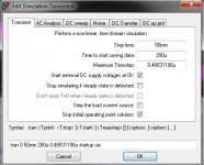
The "AC" voltage applies to a frequency response sweep, but your simulation is running a transient analysis. If you intended to increase the source signal for a transient analysis, you need to change the "Amplitude(V)" parameter on the left side of the VS dialog box from 1.009 to 3 (or 3.027 if you want to increase it by a factor of 3).
The "AC" voltage applies to a frequency response sweep, but your simulation is running a transient analysis. If you intended to increase the source signal for a transient analysis, you need to change the "Amplitude(V)" parameter on the left side of the VS dialog box from 1.009 to 3 (or 3.027 if you want to increase it by a factor of 3).
Thank you.
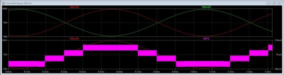
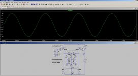
I get now good respons from LTspice, a 7 level with different way of setup the fase of the triangles can remove a lot of HD. here you can see how low it is in open loop. Interesting this on 25 amps output current.
The setup in LTspice is quite important, so I did have learn some here again. thanks for that.
The setup in LTspice is quite important, so I did have learn some here again. thanks for that.
Attachments
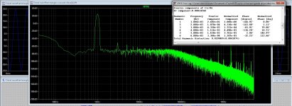
I have sometime problems with LTspice 64 bit, not always, it seems to does sometimes very strange with his outputs, get sinusoidal on speaker output resistor but the other two connections who is a voltage does give a line with kilowatts spikes.
I have als discovered that I have still two old ltpsice programs installed, the X86 and a much older X86, can these do give trouble? maybe she was the cause of missing some designs, need remove them .
I did try to find the unity gain point for the 5 level pwm amp, normally the Nquist theorem is used, somebody has a tip how to find the unity gain?
Attachments
I am modelling an amplifier in LTspice.
Now I would like to study the harmonic structure - not just the percentage, but the phase.
How can I do that in LTspice?
I was thinking of using a Laplace transform to do it, it must be a high pass function with a steep edge to when I input say 1.000 Hz, I can see the 2 Khz 2nd harmonics separately. Specifically to see what the phase will be at the operating point.
Making the formula is quite above my skills. Who has an idea how to tackle this?
You can use an E source to make a perfect amp with the same gain as your test amp. Then plot the difference of the outputs. Add some RC filters to the input to match the phase shift.
Laplace transforms in LTspice are overrated for stuff that must be harmonically accurate. They rarely work well when I have used them, they seem to be prone to generating their own harmonic noise, probably a result of the math translating poorly to realtime algorithms.
Laplace transforms in LTspice are overrated for stuff that must be harmonically accurate. They rarely work well when I have used them, they seem to be prone to generating their own harmonic noise, probably a result of the math translating poorly to realtime algorithms.
As Interface of LTspice is pretty "primitive" and not user friendly (to be polite ;-), I wonder is we could not work on a GUY interface (if this do not yet exists) that could write the good settings directly in the asc files for each of the usual works we need in audio, in order to simplify and save our time and efforts in our the daily use and benefit of the user's experience on optimized settings.
The square wave generator that is missing (how is-this possible ? ), all the good settings to tune the FFT and distortion evaluations in "transient" in order we just need to set the frequency and level, automatic change from AC to Trans in one clic (changing text in the schematic interface is so awfull), etc.
A community work.
What do-you think ?
Last edited:
...What do-you think ?
Go here Ngspice, the open source Spice circuit simulator - Intro and do your best 🙂
You use the 'Pulse' option to define any squarewave you want to create. It gives total control over rise and fall times as well as on/off period.
Post #31:
https://www.diyaudio.com/forums/sof...g-ltxvii-beginner-advanced-2.html#post4032832
Post #31:
https://www.diyaudio.com/forums/sof...g-ltxvii-beginner-advanced-2.html#post4032832
It was much easier to use before LTspiceXVII. I have not met a single person who thinks the interface changes are a good thing.
Still, just try using any other other free simulators.
Still, just try using any other other free simulators.
LTSpice UI
Every program has a learning curve, and it takes a while to find where the "bodies are buried". In that respect, I've always felt that LTSpice actually did a pretty good job on the program itself. Much of it seemed quite intuitive and natural. Of course, there are few things that seem "hidden" at first, and the documentation is a bit telegraphic, but then there's always google to help find the answers.
Even if someone put another GUI on top of it, you'd need to find those special places thru the GUI to do the tasks you mention. Of course, if you were the one spec'ing out the GUI, it would seem completely natural to you, as you had made the map.
Perhaps an in-between but useful thing would be a collection of a few example files with a bit of annotation. That probably exists somewhere on the net, and probably even on diyaudio, like this:
Installing and using LTspice IV (now including LTXVII). From beginner to advanced.
Good luck with your LTSpice learning curve...although I can drive it pretty well now, I do recall the frustration finding certain bits, but my overall impression is of a tool with a largely intuitive interface that works very well.
- Home
- Design & Build
- Software Tools
- Installing and using LTspice IV (now including LTXVII), From beginner to advanced