Originally Posted by GM
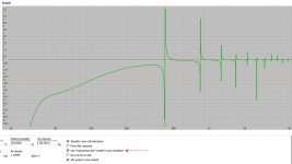
WinISD can't sim the 1/4 WL pipe action's impact on the driver's mid bass response.
Actually it can. Under the Advanced TAB you'll find that opton 😉
Attachments
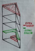
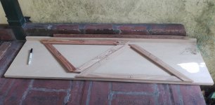
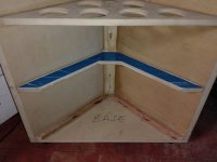
Reinforcements templates of the lower compartment. (green in the drawing)
I was thinking whether to lock the speaker back against the vertex to give greater strength to the whole ....🙂
(I read that somewhere here)
I was thinking whether to lock the speaker back against the vertex to give greater strength to the whole ....🙂
(I read that somewhere here)
Attachments
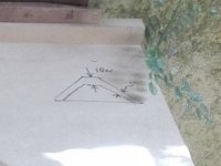
100 x 50 x 18 mm are the measurements, the big question is whether to place the reinforcement displaced from the midpoint so as not to obstruct the rear ventilation of the speaker and also not to form two panels of identical dimensions and resonances, or two reinforcements (above and below). under the engine) to achieve more strength ?
Can so much bracing´s be necessary? Is this audible ? 😕
Please help for me ...
Can so much bracing´s be necessary? Is this audible ? 😕
Please help for me ...
Attachments
Boxes, frames, etc., historically were clamped to sufficiently rigid/massive tables so that they could be twist tested, so in your case, once it can't be twisted at all, you're done........ except now there's still the issue of panel 'drumming' and for a 'sub' woofer one ideally needs it to 'ring like a bell', which when making it out of wood normally requires very rigid material [high MOE] + some bracing. FWIW, my test is to be able to stand an old square edged coin on end and have it not 'walk' or fall over when driven at high power in the LF. Takes quite a bit of 2x4 bracing 'skinned' with 3/4" marine grade no void plywood for dual low Xmax 15" in ~30 ft^3 and why I built them like a small house.
GM
GM
Ideally you break it up into odd order [3rds, 5ths, etc.], and areas at golden or acoustic ratios if triangular; whereas when in parallel, just have to space them apart at golden or acoustic ratios.
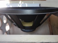
As I mentioned earlier, best to have good vertical airflow and a motor brace. Said brace should be clamped to both add rigidity and tie the driver to the cab, i.e. make it a key component of the cab's bracing. Here's a common way [slight gap filled with felt or similar such that when the driver is torqued down, it provides just enough pressure to preload the driver without bending/cracking the driver mounting flange: http://www.frugal-phile.com/boxlib/GM-A10-MLTL.pdf
GM
GM, you have convinced me. The plan of your link attached is very clear about it. Then I will do two bracing for each speaker making a stop with the engine.
The bracings in a horizontal sense will remain this way for practical reasons, they are already installed and I want to listen to these subwofers this year!
But maybe I can play with the filling to favor air displacement in the vertical direction, I thought about filling the base compartment making it very compact, less pressure in the middle and uncompressed (only loose) in the upper compartment.
I think that can help, although it is impossible to calculate. If in total I get a virtual increase of ~ 20% I think I'll be fine ...
Thank you !
I was calculating the two reinforcements to lock the speaker against the posterior vertex .....
I mention two because in that way the ventilation space of the motor would be free.
Of course I could also do it with a single reinforcement, in the center and make a cut in it so as not to obstruct the speaker's vent.
But ... will I get a really audible result with so much extra work?
Decidedly my answer and decision is: NO 😱
So General Motors ( GM) this time will have to leave the tip to Ford Motor Company ( FMC) and accept their defeat.....😀 😉
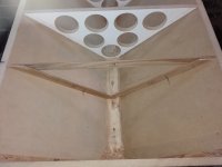
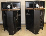
I built a single reinforcement for each cabinet, lightly displaced from the center, with enough space to not obstruct the vent, and a marble plate on the entire surface of the base will give a solid settlement against the floor, achieving a better coupling with the floor and therefore a greater room gain to be really 2 pi.
I have noticed that the rubber feet / screws (pseudo spikes) make the cabinet somewhat unstable, here three points of support are more a disadvantage than a benefit. Easy to balance, but less distribution of vertical forces (settlement) against the floor. They will be eliminated, but for now they have a function that is easy to carry without the need to carry the weight on my back and legs ...... which are already quite battered!
Osvaldo, I'm sorry, but there will be no wheels either, when the entire surface of the base is seated, the dust will not accumulate under the cabinet .....
Oh ......... but ... 😕 and how will I locate the connection terminals? I thought to do it in the space between the feet and the bottom panel ....
How is this usually done in the corner cabinets? (like the famous Klipschorn) Can someone give me information about it ? 😱
I mention two because in that way the ventilation space of the motor would be free.
Of course I could also do it with a single reinforcement, in the center and make a cut in it so as not to obstruct the speaker's vent.
But ... will I get a really audible result with so much extra work?
Decidedly my answer and decision is: NO 😱
So General Motors ( GM) this time will have to leave the tip to Ford Motor Company ( FMC) and accept their defeat.....😀 😉
I built a single reinforcement for each cabinet, lightly displaced from the center, with enough space to not obstruct the vent, and a marble plate on the entire surface of the base will give a solid settlement against the floor, achieving a better coupling with the floor and therefore a greater room gain to be really 2 pi.
I have noticed that the rubber feet / screws (pseudo spikes) make the cabinet somewhat unstable, here three points of support are more a disadvantage than a benefit. Easy to balance, but less distribution of vertical forces (settlement) against the floor. They will be eliminated, but for now they have a function that is easy to carry without the need to carry the weight on my back and legs ...... which are already quite battered!
Osvaldo, I'm sorry, but there will be no wheels either, when the entire surface of the base is seated, the dust will not accumulate under the cabinet .....
Oh ......... but ... 😕 and how will I locate the connection terminals? I thought to do it in the space between the feet and the bottom panel ....
How is this usually done in the corner cabinets? (like the famous Klipschorn) Can someone give me information about it ? 😱
Attachments
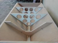
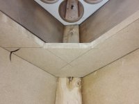
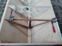
The reinforcement is already glued and screwed...
It is an irreversible fact. 😎
100 x 60 (increase the width here) x 18 mm thick.
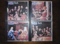
The Art of Fugue of J.S.Bach's is anxious waiting for this subwoofer to finish, WAF as well. 😀
It is an irreversible fact. 😎
100 x 60 (increase the width here) x 18 mm thick.
The Art of Fugue of J.S.Bach's is anxious waiting for this subwoofer to finish, WAF as well. 😀
Attachments
Last edited:
re: Klipschorn's basshorn terminals - it used a two screw barrier block as such with two screws (top ones) which ran though the side-wall from the inside. Ring terminals were used to connect wires to the woofer

speaking of J.S. Bach type stuff - have you heard this Lionel Rogg performance
of Buxtehude's music on pedal harpsichord ?
YouTube
speaking of J.S. Bach type stuff - have you heard this Lionel Rogg performance
of Buxtehude's music on pedal harpsichord ?
YouTube
Last edited:
Thanks freddi 🙂
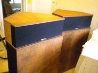
That bridge of connections is easily available here...
From what I can see in these pictures the shape of the Klipschorn cabinet has ample space so that the connection bridge is far from the wall.
Not my case, although moving a little away from the wall cabinet would be the matter solved.
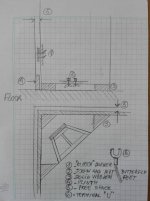
But I am thinking about placing three solid feet of wood, and in this way making the connection with screws / wing nuts, and "U" connectors.
That way the connection could be easy without using screwdrivers and could bring the cabinet to the maximum against the lower base of the wall.
I leave a sketch so that it is understood.
Also first I must put the front panel, make the hole for the speaker, etc.
Time to time....
-------------------------------------------------------------
I had not heard that version, very sweet, and with many variations, thank you !
The performer is not Wanda Landowska, but he defends himself enough ... it hurts that the recordings of her are so bad ......😀
I really like the sound of the clavichord and the variants of this instrument, which I always forget, here's something:
Clavichord - Wikipedia
It is ideal for listening in home rooms because the recordings are usually made in medium rooms, because their sound intensity is not as high as for example that of a piano.
That bridge of connections is easily available here...
From what I can see in these pictures the shape of the Klipschorn cabinet has ample space so that the connection bridge is far from the wall.
Not my case, although moving a little away from the wall cabinet would be the matter solved.
But I am thinking about placing three solid feet of wood, and in this way making the connection with screws / wing nuts, and "U" connectors.
That way the connection could be easy without using screwdrivers and could bring the cabinet to the maximum against the lower base of the wall.
I leave a sketch so that it is understood.
Also first I must put the front panel, make the hole for the speaker, etc.
Time to time....
-------------------------------------------------------------
I had not heard that version, very sweet, and with many variations, thank you !
The performer is not Wanda Landowska, but he defends himself enough ... it hurts that the recordings of her are so bad ......😀
I really like the sound of the clavichord and the variants of this instrument, which I always forget, here's something:
Clavichord - Wikipedia
It is ideal for listening in home rooms because the recordings are usually made in medium rooms, because their sound intensity is not as high as for example that of a piano.
Attachments
Last edited:
here's one piece I like a lot
YouTube
for unique sounds, are you familiar with the "Siena Pianoforte" ? (its reported to be somewhere in Israel these days) this upload sounds "remastered", in good shape and less "tubey" than the old uploads from original LPs
YouTube
your sub should be very nice once completed.
YouTube
for unique sounds, are you familiar with the "Siena Pianoforte" ? (its reported to be somewhere in Israel these days) this upload sounds "remastered", in good shape and less "tubey" than the old uploads from original LPs
YouTube
your sub should be very nice once completed.
I prefer Joaquín Sabina: one of the best CD's I have is "Nos sobran los motivos" (live) y "En directo" de Joan Manuel Serrat.
I prefer Serrat over Sabina, although I think that in this forum they do not know anything about any of them ......
Surely if in a Spanish forum, man ! 😀
Prefiero a Serrat sobre Sabina, aunque creo que en este foro no saben nada de ninguno de ellos......
Seguro que si en un foro español, hombre ! 😀
Surely if in a Spanish forum, man ! 😀
Prefiero a Serrat sobre Sabina, aunque creo que en este foro no saben nada de ninguno de ellos......
Seguro que si en un foro español, hombre ! 😀
your sub should be very nice once completed.
Thank you, I hope your wishes are fulfilled ! 🙂
for unique sounds, are you familiar with the "Siena Pianoforte" ? (its reported to be somewhere in Israel these days)
The Siena Pianoforte
I just found out about the wandering pianoforte, it's a very interesting story...

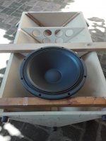
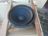
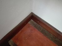
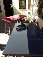
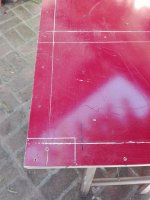
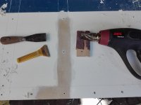
We must eliminate the paint in the areas that will be glued, the task is done with the heat gun, spatula, and sandpaper.
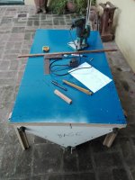
I have another question here, should I place the speaker completely on the outside or make a cavity with the router? The latter will weaken the deflector if it is too deep .....
Deep 1/4 ? 1/2 ? 😕
What do you think? Any suggestions ? 🙂
I have another question here, should I place the speaker completely on the outside or make a cavity with the router? The latter will weaken the deflector if it is too deep .....
Deep 1/4 ? 1/2 ? 😕
What do you think? Any suggestions ? 🙂
Attachments
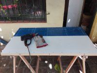
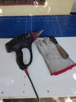
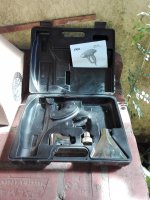
I have one of them. I used it to make the fountanery at my house: very good for soldering copper and bronze with tin alloys.
- Home
- Loudspeakers
- Subwoofers
- Eminence Delta Pro 18 A in prism sealed 150 liters