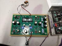
Yes, that build looks good!
I wonder how much lower noise you get by using screened cable vs just twisted pair (I have so far ended up with twisted pairs because of "laziness").
Are you satisfied with the performance of the Blue ALPS? when I measure my ALPS there is a tiny difference between channels. Probably below what can be detected in a blind test.
When you put the top on these Galaxy chassis......you don't find the applied screws a bit on the short side to be able to grab the nut every time?
I have sliced in a piece of cardboard to raise the nuts a bit......and this solved the issue.
@avdesignguru
Excellent and clean build. I am almost done with mine but using Salas 1.3 PSU with a 0-23v trafo to power the buffer. How did you connect the Alphs pot to the buffer board along with the Select 2 switch? Fortunately I have the same switch but with DACT type 50K log pot from eBay. Let me know the connections if you can via a simple diagram.
thanks
I recently completed the build and everything went well in the initial power up, balanced to recommended voltages then let it continue to warm up and rebalanced to the recommended 9.5v. However after about 20 minutes of operation on channel dropped significantly and the best t7 measurement is 4v even with the pot maxed out. Your expertise and insight is requested. Do I have a bad/faulty part? What other things can I do to troubleshoot?
The other channel remains stable at the set 9.5v
The other channel remains stable at the set 9.5v
Would someone be kind enough to give me some clues regarding the few questions I have for this built ? I read Papa’s papers but sadly I have no experience with pres and Class A – but I do have with power amps and Class A/B, where caps decoupling and no caps in signal path are of interest IMHO.
CAPS IN SIGNAL PATH
There are 3 caps (10uF) in the signal path : At the entry, between 2 stages and at the output. I read one can play with values at least in the entry (trade off bandwith I guess), but I would like to understand what these caps are for and if they are really required in my very own case.
1. Entry cap, I guess this is only to protect from DC at the input, right? If my sources don’t have large DC, is it OK to leave it out… or am I missing something ? Further, if I leave this cap out, I understand I take though a risk if an « unknown » source is plugged in, but in that case, wouldn’t the second cap (between the 2 stages) simply block any amplified DC by the first stage, end of story ? Or in that case should there nevertheless be an entry cap to protect that first stage that might not like DC ? Very confused, sorry…
2. Cap between the stages. I understand that one is mandatory regardless, right ? Now does it really have to be 10uF or can it be a lower value? Thinking quality PP 4.7uF cap, but perhaps there is a trade off going for 4.7 (or whatever lower) instead of 10uF ?
3. Output cap… Do I really need it there if there is already an entry cap at the input of my following power amp, isn’t that redundant in my very own case ?
PS CAPS
In a Class A/B it makes sense to have caps that can follow quickly the music signal, that is often having several large caps in parallel and also small quality ones to bypass them. Here it is a triple RC filter, something I see more in Class A that runs (so I understood ?) constant stable current, not necessarly having to be « reactive » so again I am clueless on this…
A )The three 2200uF (or 1000uF) filter caps in the triple RC PS-filter, apart going for higher values (PS surge permitting) does it make sense to bypass them also with smaller values to help frequency response and ESR ? Or is that useless due to the nature of that filter (but then why should one seek for quality caps with low ESR) ? I was thinking bypassing wound’t perhaps make sense on the 2 outside caps as they are « damped » by R, but on the central cap that is directly linked to « +F » that could make indeed sense to enhence the PS response…
B) Same question for another cap that seems indeed directly coupled to the output Q1, the one on the latest schematic next to the 332K resistor. That one seems in direct line between power rail and ground, while being this time directly connected to Q1… critical for the sound ?
C) Same for the cap that is between H and the ground, feeding directly the triode.
Of course not questionning the design, but I read Papa said there were some flexibility regarding all these signal and PS caps, so I merely try to understand what they stand for to make the most of it for my very own built…
Many thanks in advance for your help
Claude
The store is out of stock, and payday is coming up. 🙁
Couple hundred arriving here next week.
.........Many thanks in advance for your help
Claude
have no time now for proper answer , will do later
in a meantime , just think of DC levels at both sides of each cap in signal path, and you'll know reason for each
remember - single rail supply
Thanks Zen Mod... A bit clueless despite the hints so I will follow with great interest your proper answer whenever your time allows it.
Many thanks in advance, it is very kind of you to have taken notice of my (probably dumb) questions
Claude
Many thanks in advance, it is very kind of you to have taken notice of my (probably dumb) questions
Claude
.......
Claude
no dumb questions
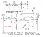
this is it ; all voltages in red strictly DC
Attachments
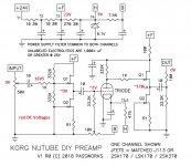
Not to nit pick but the output of the first buffer should be ~16.5V, not ~0V.
Otherwise very clear and concise explanation.
Otherwise very clear and concise explanation.
OK, thanks Zen Mod for all your effort, appreciated.
I am not sure I understand it all, but this is what I understood...
- The 3 caps in the signal path are indeed required to block DC, regardless my input and output as otherwise boom!
=> However, why 10uF? Can I get away with 4.7uF on these 3 locations, I intend to use Wima MK10s... note these PPP aren't polarised, but that shouldn't be an issue in our case, or am I missing something? Or are these 10uF critical values, or the recommended caps carefully chosen (I thought that was just VFM choice)
- Regarding the PS caps, I don't get it. Would any cap benefit from additional bypassing by quality caps or not? The ones that are 'shielded by a resistor, I guess not, but the ones directly attached to a part perhaps (the middle one of the 3 PS caps that goes straight into first stage Q1, the one between ground and last stage Q1 and clueless about the one at the triode and ground)?
Sorry again for the questions, I am absolutely not familiar with this... but very motivated ti understand and build one 🙂
Thanks again
Claude
NP stated in literature that caps down to one microfarad would work with only a small fall off in low frequency i.e. lose 2Hz. Polypro types are fine. I used 2.25 microfarad polypros, and they seem to do the trick.
on input , there is 332K/2 for Rin
as F=1/(2 x Pi x R x C) , if you choose safe 5Hz as lowest proper F , then you can go even with 220nF for input cap , and 1uF being more than generous
reason why Pa put 10uF in all 3 positions is most probably to unify things , 10uF Elna Silmic being already by Greedy Boyz officially approved syrupy part
second one need to be roughly 5 times bigger than first one , taking in account 33K or smidge more as Rin of toob part
output cap size really depends of Rin of next stage (amp or whatever) , so calc it by your self
Thanks cjfrbw...
Yes, I did read that indeed aswell... but I thought that comment from NP would only apply to the first cap in the signal path and not necessarly to the 2 others. Do you confirm that comment applies to all 3 caps in the signal path?
Note: I was under the possibly wrong impression it was only the first cap and that cap value would have been in conjunction with the volume pot, forming an input RC high pass filter. But I do understand... that I probably understood nothing LOL!
And yes, I had noticed your build and these nice brown 2.25 caps, in fact they inspired me, thanks.
That's the beauty of DIYAUDIO, you always learn something... thanks again for helping guys!
Claude
Ah, thanks again Zen Mod... post crossings but at least you confirm I wasn't completely wrong on the input and output caps dimensioning... thanks!
That closes hopefully the topic caps in signal path... what about my comment re bypassing some of the PS caps, should I forget about that as useless?
Thanks again for your time, lot of progresses for me!
That closes hopefully the topic caps in signal path... what about my comment re bypassing some of the PS caps, should I forget about that as useless?
Thanks again for your time, lot of progresses for me!
Last edited:
if you're going to sleep better , bypass those caps
Papa is sometimes lazy same as stubborn (at least we can have that impression ) , but never underestimate his sense - what is important and what isn't

Papa is sometimes lazy same as stubborn (at least we can have that impression
) , but never underestimate his sense - what is important and what isn'tI tried Pass Korg build with First Watt M2 for several hours: digital source to Pass Korg to First Watt M2 to 4 ohm crossover-less panel speaker.
In switching the polarity of the speakers back and forth, I preferred the H2 negative slightly (speaker polarity reversed) with M2.
I think Pass Korg and First Watt M2 are an excellent combination. I am a little miffed because I think the Pass Korg build does better than my beloved tube rectified DHT gain stages in this regard.
I let the First Watt M2 warm up for several hours. I would say the sound is pushed about 30 to 50 percent toward a VFET type sound, without sacrificing the organic whole-ism and energy that are M2 predilection. The combination of Pass Korg and M2 produced outstanding separation while retaining body, tone and timbre. Imaging is huge and deep.
It is very strange to me that two components i.e. M2 and Pass Korg, both with higher distortion profiles, no feedback, etc. rather than ‘the point 0000 etc.’ distortion type components, can nonetheless sound surpassingly transparent through speakers when played together. So I guess the psycho-acoustic mysteries of the distortion profiles prevail.
- Home
- Amplifiers
- Pass Labs
- B1 with Korg Triode