Improvements over Pete's stock
I think I remember a post where someone did a bullet point list of improvements reported here as advisable (bulbs on input, THAT ICs, etc). I have not saved that... Anyone has it handy, perchance?
Thank you.
Got it to work by reversing the IN/OUT. Here's the new spectrum. I guess I need to implement the improvements reported here, and think on the power supply (battery? USB?).
I think I remember a post where someone did a bullet point list of improvements reported here as advisable (bulbs on input, THAT ICs, etc). I have not saved that... Anyone has it handy, perchance?
Thank you.
Right, but that is only about choosing the right USB socket (if available). Viewing the usb tree is trivial, I assume anyone working with USB audio for measurements should have this under control.
You would be surprised how few are aware of these issues. And the difference between the various types of USB transfers. its the classic "its so fast how could it possibly not keep up" issue. And on most PC's its not easy to tell which USB thingy is on which controller from the jacks. You need to look at the tree.
I think I remember a post where someone did a bullet point list of improvements reported here as advisable (bulbs on input, THAT ICs, etc). I have not saved that... Anyone has it handy, perchance?
Thank you.
I think it's AndrewL's #326 I was thinking of (though there were improvements past that message, such as the light bulbs on input). Still unsure which THAT ICs replace what. It would be great if there'd be a single repository for the modifications from original... Especially at this point in the game where this has matured fully. But that's very time intensive.
Modifications
I earthed the body of the rotary switch during construction so I don't know how much difference it made.
I found that lining the case with mu-metal made a huge improvement in performance.
I fitted all the additional capacitors under the board and tried the THAT parts but there wasn't much improvement.
As I said before, when I started testing real amplifiers, the difference between the standard and THAT parts was inconsequential.
I found that lining the case with mu-metal made a huge improvement in performance.
As I said before, when I started testing real amplifiers, the difference between the standard and THAT parts was inconsequential.
You must be in a place with lots of LF magnetic fields. Keep in mind that MuMetal needs to be hydrogen annealed after any extensive bending or its magnetic properties degrade.
Most real amplifiers are not as low distortion or noise as the THAT parts so they are not necessary. The light bulbs on the input are a good protection option since the off resistance is 1/3 the on resistance so the input noise is lower. They need to be in series with a high impedance input or they will compromise the distortion and you need good low C diodes to the protection rails with them.
Does the effect of the bulb's lower serial resistance balance out the large size of the unshielded bulb, picking noise?
Any recommended source of mumetal shielding? Maybe there was a group buy (anyone has any left past their build?). Also, what's the best type - winded foil by the ft, or square and flat sheets? Application recommendations? (How to stick on the inside of box)
Then there's the spray... All this pretty pricey.
Then there's the spray... All this pretty pricey.
Would a non-magnetic material like copper suffice instead of mu-metal, i.e. just electrostatic shielding?
That is what I thought. Honestly, I think using a metal enclosure instead of the plastic one would bring a noticeable improvement.
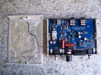
I just found some aluminum foil sufficient. Just be sure not to work with the JIG close to noises lamps, cellulars, etc.
I'm assuming you've grounded the foil?... If yes, how did you make the connection (a bit visible in the pics, but wondering if you've found some detail particularly useful).
I wonder if copper foil would be a marked improvenent over aluminum. Al would make it effectively free, though.
Last edited:
Copper tape is very easy to use and perfectly solderable - I shield everything with it
E.g. 50mm x 3m EMI Copper Foil Shielding Tape Conductive Self Adhesive Barrier Guitar | eBay
E.g. 50mm x 3m EMI Copper Foil Shielding Tape Conductive Self Adhesive Barrier Guitar | eBay
I'm assuming you've grounded the foil?... If yes, how did you make the connection (a bit visible in the pics, but wondering if you've found some detail particularly useful).
I wonder if copper foil would be a marked improvenent over aluminum. Al would make it effectively free, though.
Yes, top and bottom foiles are grounded, as well as the range selector chassis. All converge to the rear power button ground.
Of course the foils are insulated to prevent shorts with the PCB!
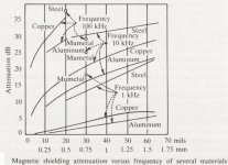
Shielding materials are quite intriguing, and as always happens, there isn't a
perfect material for all the purposes. Shielding attenuation depends on the frequency you want to filter. Attached a graphic explanation: till 100k Hz Mumetal is the best, after that frequency, no more......
Attachments
ARTA calibration with PMI in the circuit
I'm running into some puzzling scenarios with calibrating this (sorry, this is a little long). I typically have it inserted in the left channel circuit, though when calibrating each channel at a time, I'd swap symmetrically.
The first calibration was with just the 2i2, and I ended up with some level adjustment of input sensitivity of the channels to keep them out of clipping (about 10 o'clock). I have not touched this in subsequent steps. This was likely somewhere close to -3dB, and it calibrated output to about 1.6V RMS on the calibration value window (still working on understanding exactly why).
I think at this point I started getting a reading of 3.7V RMS from built in volt meter (confirmed with external DMM). Then I did just the left channel with PMI inserted. Somehow, I ended up with indicated -21dB levels on the left and the same -3dB on right. Another calibration, this time of both channels, brought both similarly on the same values, though the dB reading on the spectrum screen stays the same (about -21dB and -3dB). I can't dial the GEN OUT levels away from 3.7V RMS regardless of calibration conditions (and how exactly this gets dialed in is still a mystery to me). I'm sure there's something I'm missing (such as how ARTA thinks).
ARTA calibration with PMI in the circuit
This post is rather confusing and difficult to understand.
I assume you've been through §1.4 Audio Hardware Setup.
Are you following the instructions in §1.5 Calibration?
If so, at what point are things going awry?
This post is rather confusing and difficult to understand.
I assume you've been through §1.4 Audio Hardware Setup.
Are you following the instructions in §1.5 Calibration?
If so, at what point are things going awry?
I fitted all the additional capacitors under the board
Not sure what "additional capacitors" you are talking about. Could you elaborate?
Not sure what "additional capacitors" you are talking about. Could you elaborate?
Back in post #599.
EMI shielding
Just ran across this interesting thread.
Beside Mumetal I've also been using this material for EMI shielding:
YSHIELD(R) Magnetic field shielding film MCF5 | MF | Width 5 cm | 1 meter | Magnetic field | Sheet products | YSHIELD Worldwide (Outside EU)
They present EMI attenuation measurement results well into the GHz range.
For example, I used it to shield my MC RIAA preamps (80dB gain at 50Hz), built into Al housings. It got me rid of mains hum from a line preamp on which the RIAA one is situated.
Regards,
Braca
I was going to effusively report lower noise figures after Cu shielding and grounding the shaft last night, but at the end of it I thought it'd be "interesting" to use the wrong supply (identical jack) - 12V from my headphone amp - to supply it. Given the clamp diode on the PS input and the resettable fuse, I thought everything would survive. But now upon turn on I see the volt meter showing some numbers (may be its turn on sequence) and then shuts down. I didn't yet get a chance to inject signal through it to see if/how it passes etc. I think I insulated the copper foil pretty well, I don't think anything shorts against ground/foil. Maybe I didn't wait enough for the fuse to recover? Other thoughts?
Obviously - so I won't be misinterpreted - I simply grabbed the wrong cable, that's why. Past realizing my flubber and consequent loud slap on the forehead, is when I became hopeful the protections worked. To me, still looks like the fuse needed more time to recover. I haven't gotten a chance to get back to it yet.
- Home
- Design & Build
- Equipment & Tools
- Test & Measurement interface for Soundcard