I've got a DMM as well.. not sure how thats related to the issue on the sound card interface?
Anyhow, I found something abnormal which could be related. I generated a 60hz sine wave in ARTA with my DMM connected to GEN OUT. With GenMon enabled, rotating the range switch changes the measured voltage. For example, range is set on 20V and both my DMM and interface show 3.06V. If I rotate the switch to 2V, the interface shows the overrange sign, and my DMM shows 4.3V. So the display is correct, the issue is that changing the range with GenMon changes the measured voltage. I am assuming this is not expected?
With GenMon disabled, the DMM measures 2.8V and its the same no matter how I rotate the range. Thougts?
Trying to debug an issue with my recently built interface.
I can only suggest the usual and painful process of confirming all component are in the right places, measuring and confirming values in situ where possible and looking for shorts under the board.
Confirm the meter readings with an autoranging DMM. When power levels matter (like ensuring 1W into 8Ω) I use a DMM. I've found it to be more accurate than the built-in meter.
so I put a kit together
Ordered the board and panels from Pete along with all the parts from digikey/mouser on Monday. Received the board on Tuesday (good job Pete) and the parts on Wednesday. Finished assembly this morning. It zeroed out fairly well. A little bit of variance at the upper end of the scale from the Fluke DMM. Haven't put it on the scope yet. I did test and log all the resistor and capacitor values if anyone is interested.
Anyway, it went together with no surprises and I expect it'll work the same. Will do some testing this afternoon and in the morning. Overall I'm impressed with the quality. Only quibble and it's really minor is that the pads for many of the capacitors were a bit small for my soldering iron tip.
Attachments

I did test and log all the resistor and capacitor values if anyone is interested.
I would interested please phredrick, just recieved my board, now I have to order all the parts! Anyone who has an updated BOM it would be appreciated!
Not sure about the case, based in the UK is that something I can order on mouser or farnell? I can always 3D print something.
Thanks
You should check out Jan didden auto ranger, there's a thread here on diyaudio, a really neat device,
I would interested please phredrick, just recieved my board, now I have to order all the parts! Anyone who has an updated BOM it would be appreciated!
Not sure about the case, based in the UK is that something I can order on mouser or farnell? I can always 3D print something.
Thanks
I’ll post the values in an hour or two. I bought the case and most of the parts from digikey. The current BOM on pmillett.com is accurate. I can send you the BOM csv file I used with digikey’s website. There are a few part substitutions which are covered in Pete’s notes on the BOM. If anything isn’t clear then just ask and I can list manufacture’s part numbers for specific items, but Pete has already listed nearly everything.
Component values in attached pdf
Attachments
I would interested please phredrick, just recieved my board, now I have to order all the parts! Anyone who has an updated BOM it would be appreciated!
Not sure about the case, based in the UK is that something I can order on mouser or farnell? I can always 3D print something.
Thanks
The case is still available from mouser: nr. 563-PC-11403
I did use a different DVM module in my EU build.
I’ll post the values in an hour or two. I bought the case and most of the parts from digikey. The current BOM on pmillett.com is accurate. I can send you the BOM csv file I used with digikey’s website. There are a few part substitutions which are covered in Pete’s notes on the BOM. If anything isn’t clear then just ask and I can list manufacture’s part numbers for specific items, but Pete has already listed nearly everything.
Very much appreciated phredrick, saves me time that i do not have currently, BOM csv would be great, means i can quickly work through, learn the board and order the components.
First time building something like this so no idea what i am doing, hoping it's plug and play when all the necessary adjustments are made.
Eager to get this working to test the performance of various amps i have built.
You should check out Jan didden auto ranger, there's a thread here on diyaudio, a really neat device,
I have actually amplidude, got an email through about it the other week. I bought pmillets kit first so going ahead to finishing it.
csv is attached - the csv is simply an extract of info from Pete's BOM which seems to work with digikey's BOM import function on their webpage.
The import function dumps out a list which has to be inspected/corrected for out of stock items. No big deal but a little attention to detail is important. I kept Pete's BOM open in a spreadsheet window to reference while going through the list on digikey's website. Order quantity changes and parts substitutions can be made to the list so you can purchase exactly what you want.
Another thing to do is register as a customer prior to doing the import so the BOM can be saved and the purchase made at a later time. Handy if you want to get prices from a couple of vendors.
Just in case anyone here wants to save themselves some time, I listed my PM soundcard interface up for sale this morning. I purchased it from a forum member two weeks ago but had a car issue that I had to get repaired so I need to sell the interface to recoup some of that repair fee. Being an adult sucks.
Anyway, here's the link just in case anyone is interested. Asking what I paid for it.
FS: Assembled Sound Card Interface / AC RMS voltmeter by P. Millet
Anyway, here's the link just in case anyone is interested. Asking what I paid for it.
FS: Assembled Sound Card Interface / AC RMS voltmeter by P. Millet
I generated a 60hz sine wave in ARTA with my DMM connected to GEN OUT. With GenMon enabled, rotating the range switch changes the measured voltage. For example, range is set on 20V and both my DMM and interface show 3.06V. If I rotate the switch to 2V, the interface shows the overrange sign, and my DMM shows 4.3V. So the display is correct, the issue is that changing the range with GenMon changes the measured voltage. I am assuming this is not expected?
Can anyone confirm if this is the expected behavior or not? If rotating the range knob changes the input impedance then I guess the measured voltage should change as well (given the soundcard is generating a constant signal)
You may overdriving a stage in the unit by going to a lower range which switches in more gain. If you look at the signal you probably see it is clipped. Check the circuit diagram what happens when you switch ranges.
Jan
Jan
Martin Demian, interestingly, can you describe how you connected the HP8903 to an external soundcard?
You can route the monitor output to a soundcard and do FFT analysis to see the harmonic content. The 8903 can handle the input levels a sound card cannot. The output should be well withing a soundcard's input capability.
Hi all,
I would love some assistance in running my first series of tests. The DUT in this case is a DIY headphone amp I built a while back. It is connected to a 100R resistor I _think_ all of my connections are correct.
I'm running the tests on my PC with Windows 7 and an E-MU 0404 PCIe card.
The things I'm unsure of right now are:
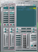
1) Are my E-MU PatchMix settings correct?
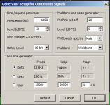
2) What are the recommended generator settings in ARTA?
3) How to set the volume control on the amp? Should the volume be set so that the output of the amp matches the input signal, fully open, or something else?
I am attaching some screenshots of a test I ran. In this case, the volume pot was set so that I read the 2.81V in the SC interface (and this voltage was confirmed correct with my Fluke 87-V DMM).
Thanks in advance!
I would love some assistance in running my first series of tests. The DUT in this case is a DIY headphone amp I built a while back. It is connected to a 100R resistor I _think_ all of my connections are correct.
I'm running the tests on my PC with Windows 7 and an E-MU 0404 PCIe card.
The things I'm unsure of right now are:
1) Are my E-MU PatchMix settings correct?
2) What are the recommended generator settings in ARTA?
3) How to set the volume control on the amp? Should the volume be set so that the output of the amp matches the input signal, fully open, or something else?
I am attaching some screenshots of a test I ran. In this case, the volume pot was set so that I read the 2.81V in the SC interface (and this voltage was confirmed correct with my Fluke 87-V DMM).
Thanks in advance!
Attachments
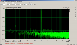
I made some progress here and I believe the FFT plots I am generating are fairly accurate, attaching one of them of a tube headphone amp I measured.
Could someone please advise what is the proper way to measure undistorted max power output?
I am unsure how to do this, as the SC interface will scale the signal. I am using ARTA for software
Could someone please advise what is the proper way to measure undistorted max power output?
I am unsure how to do this, as the SC interface will scale the signal. I am using ARTA for software
Attachments
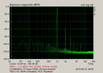
What I do: First, I find how close to 0dB my sound card can reach in loop measurement before clipping. If this point is not exceeded, then I expect that clipping should only appear at the D.U.T. and this will define max output. Just scale the PC interface so that I get closer to this dB level for a better signal to noise measurement. Lacking an oscilloscope, I find the clipping threshold using ARTA time record window. However, it's not real time record, you have to do some trial and error. Check REW for a real time oscilloscope.
- Home
- Design & Build
- Equipment & Tools
- Test & Measurement interface for Soundcard