Scott re vibrations
I would suggest to start with the electrical part of your ac motor.
Find the optimum operating voltage and the optimum phasing capacitor value for minimum motor vibration.
Thanks again, it is just a Hurst 24V motor and the mounting leaves much to be desired. Plenty to play with.
😀
Naturally the good and faithful will be 'cueing' up to buy one.
It's so funny it's sad. YouTube
I wonder if flipping the platter over by accident is fatal.
Last edited:
Thanks again, it is just a Hurst 24V
LYD42 42mm Direct Drive Permanent Magnet AC Synchronous Motors
AC frequency affects rotation speed
voltage (+/_ from nominal) affects torque and vibrations.
Phase btn the two windings should be 90degrees at frequency of operation. Phase is controlled by the phase splitting capacitor. Capacitor value affects motor vibrations too.
and the mounting leaves much to be desired. Plenty to play with.
Enjoy the trip.
If you connect the accelerometer to the oscilloscope input, you can use the “Y out “ of the scope (scope works as a buffer, amplifier, attenuator in this case) to drive the soundcard. you adjust the signal level to the soundcard using the “Y sensitivity” knob)
George
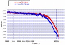
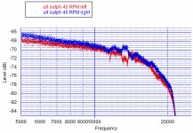
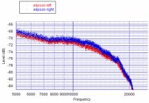
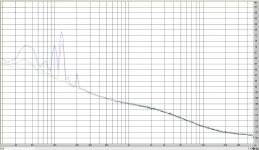
I did some recordings of pink noise 45 RPM from the Ultimate test record and the Elipson both made at 45 RPM to see whether there is anything to see higher in frequency. Now I know my cart drops of after 17 kHz, so I cannot expect to see so much resonances. For what I can see there is some wiggling in the curves 10-20 kHz especially using the Ultimate test record. These small ups and downs can not repeated with the Elipson pink noise though. So these things probably are recorded into the record.
Attachments
So these things probably are recorded into the record.
Thanks, I would venture a guess that the UTR with PN in only one channel would have some crosstalk artifacts around 13k or so as you show. I can't think of any mechanism that would manifest with such rapid variation with frequency. Spinning the LP down and listening to the supposedly empty channel makes it very obvious that it is on the LP.
The cap is 1/2 the value on the DS, a place to start.Capacitor value affects motor vibrations too.
Thanks, I would venture a guess that the UTR with PN in only one channel would have some crosstalk artifacts around 13k or so as you show. I can't think of any mechanism that would manifest with such rapid variation with frequency. Spinning the LP down and listening to the supposedly empty channel makes it very obvious that it is on the LP.
These are both recorded in mono in or out of phase so there is no possibility of either of these records to check the crosstalk. Of the records I have I can use the Ortofon to check crosstalk but those are sweeps and not pink noise. I don't thing the Tacet record has any pink noise either that is recorded in left or right only.
You can use the QA400 as a convenient spectrum analyzer to look at the vibration.
I built 2 phase motor drivers for Rockport and confirmed that small tweaks in drive level between the phases can make a big difference. As did current drive, but that's getting pretty extreme. This guy has two phase output available. Assembled Low Distortion Audio Range Oscillator 1KHz Sine Wave Signal Generator | eBay Two for two speeds. A cheap stereo amp board would give you two drive amplifiers to drive the motor. If your really nuts (I was) a time delay cuts back the drive after 5-10 seconds since you don't need as much torque.
I built 2 phase motor drivers for Rockport and confirmed that small tweaks in drive level between the phases can make a big difference. As did current drive, but that's getting pretty extreme. This guy has two phase output available. Assembled Low Distortion Audio Range Oscillator 1KHz Sine Wave Signal Generator | eBay Two for two speeds. A cheap stereo amp board would give you two drive amplifiers to drive the motor. If your really nuts (I was) a time delay cuts back the drive after 5-10 seconds since you don't need as much torque.
Well, there is also this thread. Should be quite good.
DIY 4 Phase Sinewave Generator for Turntable Motor Drive
DIY 4 Phase Sinewave Generator for Turntable Motor Drive
Thanks guys, years age I played with the idea of simply putting the waveforms on an MP3 stick player and playing them through a small PA. Worked fine for a few watts of 60Hz mains. What surprised me was how well even the worst setting of MP3 worked at a single frequency, didn't research it anymore.
That does seem a very logical way to try it out. With a RPi basic model being $5 now DDS waveforms seems a no brainer.
FLAC also manages incredibly small file sizes for repetitive waveforms
For sure, I was just curious about a supposedly lossy CODEC keeping the zero crossings of 60Hz vs 60.01Hz perfectly.
When checking to be 100% sure that all was O.K., I discovered two el. caps in the power supply of the motor drive that had complete lost their capacitance.
This resulted in awkward shapes instead of two nice sinuses driving the motor.
Everything O.K. now, again giving a perfect Lissajoux circle on the scope.
Driving the motor without belt, made no audible difference in noise with Cart on the platter or Cart+Arm in the air.
I played the CH precision disk at 33 1/3, at 45 and at 60.75rpm.
The latter is achieved when using the 45rpm TT pulley plus a 67.5Hz motordrive signal (to get 45rpm with the 33 1/3rpm pulley), thus giving (67.5/50Hz)*45rpm= 60.75rpm.
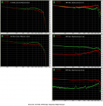
All three FR's are 96k/24 recorded and displayed at exactly the same setting and scale, and so are the 16K FFT's calculated in overlap over a 15 sec time window, just like before with the Adjust+ LP.
1) All curves end at -69dB, so far so good, but
2) why are all three curves at almost the same level at 10kHz ? I would expect three lines going in parallel.
3) why is the 33 1/3 rpm FR going down from 10K to 20K by 6dB instead of 3dB, while the other two do not show this sudden roll off ?
4) Why is the FR at 60.75 rpm making a small 1dB jump upwards at 22kHz, where the other two have no jump ?
Hans
This resulted in awkward shapes instead of two nice sinuses driving the motor.
Everything O.K. now, again giving a perfect Lissajoux circle on the scope.
Driving the motor without belt, made no audible difference in noise with Cart on the platter or Cart+Arm in the air.
I played the CH precision disk at 33 1/3, at 45 and at 60.75rpm.
The latter is achieved when using the 45rpm TT pulley plus a 67.5Hz motordrive signal (to get 45rpm with the 33 1/3rpm pulley), thus giving (67.5/50Hz)*45rpm= 60.75rpm.
All three FR's are 96k/24 recorded and displayed at exactly the same setting and scale, and so are the 16K FFT's calculated in overlap over a 15 sec time window, just like before with the Adjust+ LP.
1) All curves end at -69dB, so far so good, but
2) why are all three curves at almost the same level at 10kHz ? I would expect three lines going in parallel.
3) why is the 33 1/3 rpm FR going down from 10K to 20K by 6dB instead of 3dB, while the other two do not show this sudden roll off ?
4) Why is the FR at 60.75 rpm making a small 1dB jump upwards at 22kHz, where the other two have no jump ?
Hans
Attachments
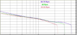
P.s. In the above image, I noticed the little jump at 22kHz also in the 33 1/3rpm curve at half the frequency, so this seems Test Record related.
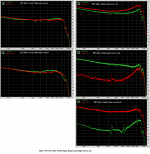
In the Image below, I've put together the noise spectra from:
1) Arm in the air, motor off in Green
2) Arm on the platter, motor off in Red
3) Arm on the platter, motor on without drive belt in Blue.
Obviously there is something at 125Hz that's coming in through the floor/table/TT feet. No idea what this can be, but I can't hear it.
With the motor on, 100Hz and 200Hz are popping up, and the 125Hz component is getting a bit stronger.
Recording was in exactly the same setup as used for the pink noise images, so at 2kHz, this noise was >-53dB below the pink noise above.
Hans
P.S. From 15Khz upwards, noise from the measuring chain at -126dB starts to interfere with the noise from the pre-amp
Attachments
Last edited:
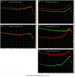
Thomas post with the FFT of pink noise from the Ultimate test LP, made me look back on some older recordings I had made.
With a different cart, things look a bit different (the glitches Scott noticed)
George
With a different cart, things look a bit different (the glitches Scott noticed)
George
Attachments
Thomas post with the FFT of pink noise from the Ultimate test LP, made me look back on some older recordings I had made.
With a different cart, things look a bit different (the glitches Scott noticed)
George
The "glitches" don't have a simple explanation.
Good Job Scott! Well the secret is out now so I might as well reveal it to all. Scott just demonstrated on a working LP Record what they used to do in the production trucks during sporting events. Yes were talking Slow-Motion replay. The guys would quickly rewind the tape and then play forward again then apply a finger to the reel to slow it down. You can image how funny it was to see Semi Trucks loaded wtih multi-million dollars worth of broadcast television equipment and see 8 or 10 guys on the tape machines slowing down the reels of the video tapes with their fingers to provide us with-- "Slow-Motion" replay was born. Because the tape heads were the helical-scan type the video never looked bad. The video tape wrapped around the rotating scan head forming a loop, so you got a full image even when the tape was stopped or slowed. Okay back to our regularly scheduled discussion.My bizzaro experiment for the week. I spun the Adjust + LP by hand down to 3 RPM or so and the crosstalk was still there, in fact it was clearly audible at low RPM. A quick look at the grooves with my USB microscope seemed to confirm there was a signal in the channel that was supposed to be blank.
Cheers,
- Status
- Not open for further replies.
- Home
- Source & Line
- Analogue Source
- Cartridge dynamic behaviour