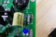
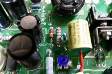
I think I found the problem but need to double check everything. After replaced the cap, and got the cap meter check that found nothing wrong. Now I realized the color is different on resistor. Compare with the original images, it's absolutely missing the red color.
Both resistors have the same value so I guess the top one is burned. Will compare all resistors on both channels to see anything else is bad. 🙂
The values are slightly different. Google resistor color codes.
One is 511, the other is 512. But I believe that the 3rd ring is a multiplier, so one could be 510 ohms and the other 5100 ohms. Did they measure the same?
Could also be 5.11k and 5.12k, that would be a 0.2% difference ;-)
Jan
Last edited:
It may be something else too but that's a good one to start.
Both resistors are the same value and in series on the schematic so they should be the same color code. It seems like both resistors on right channel has a little bit lower value than the working left channel.
Usually, I am home by myself so I am very careful to touch anything when it's on. 🙂
Both resistors are the same value and in series on the schematic so they should be the same color code. It seems like both resistors on right channel has a little bit lower value than the working left channel.
Usually, I am home by myself so I am very careful to touch anything when it's on. 🙂
Both resistors have the same value so I guess the top one is burned. Will compare all resistors on both channels to see anything else is bad. 🙂
Both resistors have the same nominal value, i.e. 5K1, did you measure them with an Ohm-meter?
Overheated resistors tend to measure a higher value.
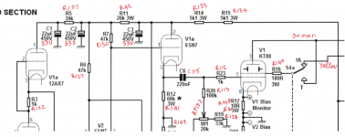
One of the 5K1 resistors is clearly overheated, in the circuit both are series connected to a 22uF/450V electrolytic capacitor, please check that capacitor.
If they are series connected and have the same value, both would be overheated the same, or none would.
Jan
Jan
22uf/450 is currently 33uf/450v, I guess manufacture upgrade the caps. All these caps are fine.
When using ohm meter, the left working channel resistor is 5.1 while the problem right channel has 4.8. On the right channel, the overheat resister has lower value than the one next to it so I assume only 1 is bad.
I have LCR-T4 Digital Transistor Tester Resistor Capacitor Tester, I will compare them later.
22uf/450 is currently 33uf/450v, I guess manufacture upgrade the caps. All these caps are fine.
The +B of your amp is very high, the first 22uF/450V cap (33uF/450V) is the most stressed on the whole amp.
When using ohm meter, the left working channel resistor is 5.1 while the problem right channel has 4.8. On the right channel, the overheat resister has lower value than the one next to it so I assume only 1 is bad.
That is weird, the power dissipated on the resistor is P = I² R, so the higher the value, the higher the heat dissipated.
Please check again 5K1 resistors and near capacitors.
Unsolder one resistor pin, and after that measure, the same for the cap.
Last edited:
Those are the type of Panasonic resistors that Digikey sold 10 to 15 years ago. I have fried enough of them to know that something caused a serious excessive current flow through the burnt one in your picture. Those resistors will lose their red, orange and yellow bands when overheated. All of those colors will turn dark brown or black. As your resistance measurements indicate, their resistance value will go DOWN slightly when severely overloaded. They may however still be OK.
Compare the two resistors in these photos. The first picture shows a perfectly healthy 27K ohm resistor that has lived a 15 year peaceful life. It measures 26.6 K ohms.
The second picture shows what happens when the dumb blond one powers up a board and watches it smoke only to find that he had set it down on a small 4-40 not which blew up one of the mosfets putting 400 volts across the resistor. I replaced the fried mosfet, and measured the burnt resistor. It measures 24.5K ohms which is out of spec, but close enough for proper operation in my circuit, so being lazy, I left it there. That was several years ago and it still works fine.
I am making the following assumptions based on the information I see here and the schematic that was posted. There could be other possibilities if the schematic is not correct, or something else has happened.
It appears that there are 4 of these 5.1 K resistors in your amp. There are two in each channel which are wired in series. It would be rather hard for one of the 2 resistors which are in series to get that burnt with no damage to the other, unless there was an accidental short from the junction of the two resistors to something.
It could be remotely possible that a short (misplaced solder blob...) on one of the new caps could have caused the 6SN7 to draw excessive current, and the "smell" could have been a 6SN7 in red plate meltdown. Did one of them glow brightly at the time the amp made a smell? If so, it could now be dead.
Attachments
Those are the type of Panasonic resistors that Digikey sold 10 to 15 years ago. I have fried enough of them to know that something caused a serious excessive current flow through the burnt one in your picture. Those resistors will lose their red, orange and yellow bands when overheated. All of those colors will turn dark brown or black. As your resistance measurements indicate, their resistance value will go DOWN slightly when severely overloaded. They may however still be OK.
As a TV repairman I see almost daily that kind of resistor overheating, and the blackened color band it is a classic, but I observed that after overheating the resistance is increased, maybe this is the counter-example.
It appears that there are 4 of these 5.1 K resistors in your amp. There are two in each channel which are wired in series. It would be rather hard for one of the 2 resistors which are in series to get that burnt with no damage to the other, unless there was an accidental short from the junction of the two resistors to something.
Yes, this is possible, nonetheless it cannot see anything suspicious on the PCB, maybe the non-overheated resistor has better heat transfer?
It could be remotely possible that a short (misplaced solder blob...) on one of the new caps could have caused the 6SN7 to draw excessive current, and the "smell" could have been a 6SN7 in red plate meltdown. Did one of them glow brightly at the time the amp made a smell? If so, it could now be dead.
Agree, but my first suspect is the cap, the voltage there is on the order of 450V.
Both are 5.1K. I have checked pt by pt and relabel them.
All 3 caps are fine - 22uF/450V cap (33uF/450V)
Both resistors on the left channel are 5.xx and the right channel with a bad one is 4.8 and the other good one is 4.9
wow, they still use the old resistors from 10 years ago. 🙂 All tubes glow equally brightness. I will order new resistors to see what happen. I turn off right away when it's smell. I think all the tubes are fine.
Attachments
Both are 5.1K. I have checked pt by pt and relabel them.
All 3 caps are fine - 22uF/450V cap (33uF/450V)
Both resistors on the left channel are 5.xx and the right channel with a bad one is 4.8 and the other good one is 4.9
wow, they still use the old resistors from 10 years ago. 🙂 All tubes glow equally brightness. I will order new resistors to see what happen. I turn off right away when it's smell. I think all the tubes are fine.
So both resistors on the right channel are overheated, then I still suspect of the electrolytic cap, and after read Tubelab_com post, a fried valve is the second suspect.
An overheated/leaky electrolytic cap is very difficult to find by common instruments unless it is very damaged.
I still suspect of the electrolytic cap, and after read Tubelab_com post, a fried valve is the second suspect.
The fried valve is too fantastic: it has a 68k in the cathode. If anything draws excessive current it can only be the cap. It is still essential to compare the current in both channels; perhaps the resistors were designed to dissipate too close to their rated power.
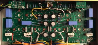
Those 3 black caps may have to take out to do a measurement? I have tool meter to check them but wonder if I can leave it there to get a measurement.
Just the one connected with the 5K1 resistor, remove it and then measure.
I cannot see the overheated resistor in the photo, so it is not updated.
And do not forget, following Tubelab_com advice, swap the valves right-left channel, maybe he is right and one was fried.
The fried valve is too fantastic: it has a 68k in the cathode. If anything draws excessive current it can only be the cap.
No, he said that accidentally a short circuit maybe occurred.
It is still essential to compare the current in both channels; perhaps the resistors were designed to dissipate too close to their rated power.
Agree, but the OP do not have courage to do it, and we must act accordingly.
The failure is consistent with a bad cap, and as I said before, the first electrolytic after the 5K1 resistors has about 450V over it and is the more likely to fail.
Last edited:
The overheated resistor image post #35 on page 4 which the red color changed to black. The image on post 54 is all original parts. I don't think it was a short circuit except the smell of burning which I turned off right a way. This is gonna hard to desolder this cap but I will try as best as I can.
The overheated resistor image post #35 on page 4 which the red color changed to black. The image on post 54 is all original parts. I don't think it was a short circuit except the smell of burning which I turned off right a way. This is gonna hard to desolder this cap but I will try as best as I can.
I can see that desolder the cap would be a total PITA, so try to swap valves first, another possibility is to make dynamic measurements which involves to work with the amp alive with high voltages all over.
If the cap is severely damaged it can be seen, maybe an updated photo will help, if not you must check the caps, be careful desoldering them.
Last edited:
Here was the original image that was working fine before
Probably the smell of burning came from that resistor. I am not sure if it's good or not. Replacing would prevent more damage in the future. I am gonna to take time to compare every single of them. Got the tool to measure the resistor now so I will check them. I am not comfortable to do the voltage check when the amp is on. 😀
what i do is to measure the voltage across those resistors, then i can calculate actual dissipation, p= e squared / resistance, if those are 3 watt resistors, and actual dissipation is 1 watt, then i know that that resistor is running hot...
if actual dissipation is 1 watt, i will put a 5 watt resistor in there...
also i lift them up from pc board, by at least half an inch to get good ventilation....
Tried to swap every single tubes around, and the same location has the burning smell so I didn't think the tubes were bad. Something is on the pcb.
I will look to see if they have 5w. what brand is the best for tube?
I will look to see if they have 5w. what brand is the best for tube?
Last edited:
Tried to swap every single tubes around, and the same location has the burning smell so I didn't think the tubes were bad. Something is on the pcb.
Not the burning smell, but the bump you heard at start-up, unless this is not the problem anymore... 🙄
What do you mean by working/not working channel? 😕
a smelly coupling cap is unheard of in a tube amp, normally the electrolytics will smell when they become bad...
also when a coupling cap becomes bad, red plating on the output tube is sure to happen,
saw this firsthand in a Fisher 500 amp with red plating in one 7868 output tube, replacing the coupling cap cured the problem, the defective cap btw, did not test bad at all, i even purchased a 600 volt megger, but the insulation seemed fine...
- Status
- Not open for further replies.
- Home
- Amplifiers
- Tubes / Valves
- If you smell the burning from the coupling caps