Just be aware that if you connect two amps at once the load to the buffer will be the input impedances of the amps in parallel. So if both amps have a 50K input impedance your buffer will "see" 25K.
Great point Steve. Thanks.
BASICS.....
Reckon I won't hear the difference in 3.18hz to 6.36hz
I got the ACF-2 working. There is a buzz though. The problem and solution is documented here
Waiting on the caps now...SIGH !
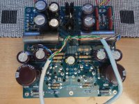
C4 now has two caps connected - the solution to the 'buzz' problem. Powered on without tubes but R7 on the left channel get really hot and starts to change to brown. Although R7 on the other channel gets hot, it does not get brown like this one. I've swapped out the R for a new piece and the same is happening. Looks like it is getting hotter than it is meant to handle.
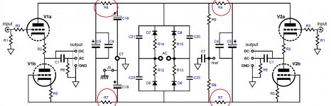
I've attached the schematic from John's site.
What could be the problem, please help? I'm testing without tubes and have checked all the solder, which looks fine.
P.S: R4 & R7 set the HT+ power supply.
BASICS.....
Reckon I won't hear the difference in 3.18hz to 6.36hz
I got the ACF-2 working. There is a buzz though. The problem and solution is documented here
Waiting on the caps now...SIGH !
C4 now has two caps connected - the solution to the 'buzz' problem. Powered on without tubes but R7 on the left channel get really hot and starts to change to brown. Although R7 on the other channel gets hot, it does not get brown like this one. I've swapped out the R for a new piece and the same is happening. Looks like it is getting hotter than it is meant to handle.
I've attached the schematic from John's site.
What could be the problem, please help? I'm testing without tubes and have checked all the solder, which looks fine.
P.S: R4 & R7 set the HT+ power supply.
Attachments

Thanks Kodabmx. In that case I have a problem somewhere.
Looks like this has started after I put the fix for C4 twin caps. How do I troubleshoot ?
I'm reading ~182v before the resistors. R4 & R7 are 4.7K.
Looks like this has started after I put the fix for C4 twin caps. How do I troubleshoot ?
I'm reading ~182v before the resistors. R4 & R7 are 4.7K.
Last edited:
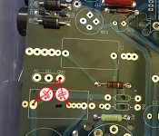
Sunil, I am reposting you photo from the other thread.
1. The cap between R7 and ground is reversed - that is, it has (-) going to the ground and (+) to R7 - and conducts DC current. It would be hot, too, and the voltage on it would be small. If there is enough current, the cap can even blow up. Did you get cap polarity right? Does R4 get hot/brown, too? It should stay cold if the other cap from the pair is connected correctly.
2. There is a short on the PCB somewhere, but it is difficult to say from the one picture provided. In this case, R7 would dissipate about 7W (182**2 / 4.7k).
Can you please check my two hypotheses and report back?
Looking at the schematic, with no tubes in sockets there are two ways R7 can get hot:They shouldn't get hot at all if there are no tubes in it...
1. The cap between R7 and ground is reversed - that is, it has (-) going to the ground and (+) to R7 - and conducts DC current. It would be hot, too, and the voltage on it would be small. If there is enough current, the cap can even blow up. Did you get cap polarity right? Does R4 get hot/brown, too? It should stay cold if the other cap from the pair is connected correctly.
2. There is a short on the PCB somewhere, but it is difficult to say from the one picture provided. In this case, R7 would dissipate about 7W (182**2 / 4.7k).
Can you please check my two hypotheses and report back?
Attachments
Last edited:
Alexcp, thanks for the analysis.
Both caps have the -ve going to ground. I followed the instruction shown in the other thread.
Glassware ACF-2 Aikido hum problem
Like this.
Here's a pic.
Both caps have the -ve going to ground. I followed the instruction shown in the other thread.
Glassware ACF-2 Aikido hum problem
Like this.
Here's a pic.
Attachments
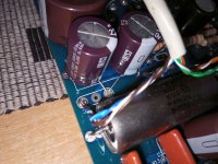
Here we go.Both caps have the -ve going to ground.
The cap between R7 and the ground should be reversed, and replaced with a new one. ACF-2 uses bipolar power supply, and R7 is the negative rail. The cap should have (-) connected to R7 and (+) connected to the ground.
Connected as is, the cap has reverse voltage applied to it. The dielectric of an aluminium electrolytic capacitor is made of a thin layer of aluminium oxide. When you reverse the voltage, the oxide becomes dissolved through electrolysis. This then allows current to pass freely between the two plates of the capacitor as they are submerged in conductive liquid, making it very low resistance between the two terminals instead of a capacitor. Wikipedia has additional detail if you're interested.
I posted this to the other thread as well, just in case.
Last edited:
Thanks Alexcp. I will make the change.
You mention that the caps should be replaced. Does that mean I cannot rewire the existing cap with the right polarity ? Are the caps damaged having run them the way they are presently ?
You mention that the caps should be replaced. Does that mean I cannot rewire the existing cap with the right polarity ? Are the caps damaged having run them the way they are presently ?
You may be right - I have no hands on experience with that. Still, I'd change them, perhaps when a good replacement is available, to be on the safe side. Even if they work, they may be out of specs after 180V / 4.7k = 39mA flowing through them.They CAN be damaged, but R7 is pretty large. They probably still work.
Thank you Kodabmx. Thank you Alexcp.
Being paranoid, that an electrical part may be compromised and fail at a later time, I am going to change the cap anyway. Another weeks wait, then test.
Will update this thread with a picture if all goes well. The time you have taken to help sole this problem is most appreciated.
Being paranoid, that an electrical part may be compromised and fail at a later time, I am going to change the cap anyway. Another weeks wait, then test.
Will update this thread with a picture if all goes well. The time you have taken to help sole this problem is most appreciated.
Is my pcb the same as you guys have been talking about?
I've had it for awhile and have been hesitant to build it due to mistakes or missing info/pages I've read about.
I'm not sure if I should try and build it or not. I'm not as tech savvy like most of you are. Troubleshooting for me might be a PITA.
Photos of my pcb added.
Thanks,
Link:
ACF-2 Octal Aikido Cathode Follower Kit
Attachments
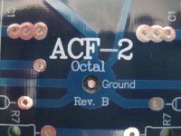
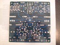
Is my pcb the same as you guys have been talking about?
ACF-2 Octal Aikido Cathode Follower Kit
Your PCB appears to be the same sunil is using. My PCB is for noval 9-pin base tubes, but it implements the same schematic.
In my view, it is an easy build; you probably will have more work drilling the enclosure than soldering the PCB. Apart from the hum issue discussed above, there is little that can go wrong as long as you follow the very complete documentation downloadable from tubecad.com and Broskie's online store.
Yes, it is the same (Octal base - 6SN<x><y> family tubes). My experience with this build is the same as alexcp has said - not so complicated. It requires a little bit of work to get the missing values and ignoring the values that don't matter. The documentation has plenty of errors.
I'll let you know in a few days, once the new set of caps get here.
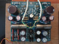
It works !
Get the cap polarity right and the ACF-2 sings. I'm running very efficient Altecs and there's no hum. Compared to earlier without the "twin-cap" mod, it is very quiet.
I will publish the values used in a few days, so it will hopefully help somebody with their build.
Thanks again alexcp.
I'll let you know in a few days, once the new set of caps get here.
It works !
Get the cap polarity right and the ACF-2 sings. I'm running very efficient Altecs and there's no hum. Compared to earlier without the "twin-cap" mod, it is very quiet.
I will publish the values used in a few days, so it will hopefully help somebody with their build.
Thanks again alexcp.
ACF-2 Resistor and Capacitor list
Here's my list of components for the build.
* Read somewhere that 10ma idle current should be fine, that worked to 4.7K for R4 & R7. Its explained on page4.
~9.7ma
Raw DC 182v (130-0-130)
V Dropper R 3K
Cathode R 320R
The regulator runs hot, definitely need a big heatsink. Use at your own risk.
The experts should chime in if there is a mistake in my understanding or what I've described.
Here's my list of components for the build.
Code:
R1	1M
R6	1M
R2	320R	(Plate R)
R5	320R	(Plate R)
R4*	4.7K	(Voltage dropping R)
R7*	4.7K	(Voltage dropping R)
R3	300R
R8	47K
R9	100K
R10	124R	(Sets the regulator low V)
R11	1K		(Heater V. Work this out, depends on your trafo)
R12	10R
R13	10R
R14	10R
R15	10R

C1	1.0 uF	(P.I.O)
C3	1000 uf
C4	220 uf x 2 (Dual cap eliminates HUMmmm)
C5	150 uF
C3	1000uf
C20-23	0.1 uF
C18-19	220 uf
C24-27	0.01 uF
C28-29	8000uF
C30-31 1000uF~9.7ma
Raw DC 182v (130-0-130)
V Dropper R 3K
Cathode R 320R
The regulator runs hot, definitely need a big heatsink. Use at your own risk.
The experts should chime in if there is a mistake in my understanding or what I've described.
- Home
- Amplifiers
- Tubes / Valves
- Glassware Aikido All-in-One (Octal) | ACF-2 Buffer