That's certainly not right.According to the schematics it's about 25uA per transistor (30V/160kohm/4/2) or 50uA/pair tail current. […]
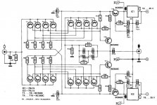
The Amp consists of paralleled differential pairs, each having it's own 136k resistor (8 in total) according to this schematic https://www.diyaudio.com/forums/att...-bc560-low-noise-riaa-sln_noise-schematic-jpg
The calculation is therefore 30V/136k/2(Diff Pair) = 110 uA
And I don't think there are some current sharing issues….
I have such a Phono Pre since many years, and for MC (low cartridge impedance therefore!!) it really excels in low noise.
However, for higher gains the feedback network is too much influenced by the input inpedance of the fllowing stage. Therefore I have added a simple complementary jFet K170/J74 buffer a la Borbely.
That's certainly not right.
The Amp consists of paralleled differential pairs, each having it's own 136k resistor (8 in total) according to this schematic https://www.diyaudio.com/forums/att...-bc560-low-noise-riaa-sln_noise-schematic-jpg
The calculation is therefore 30V/136k/2(Diff Pair) = 110 uA
And I don't think there are some current sharing issues….
I have such a Phono Pre since many years, and for MC (low cartridge impedance therefore!!) it really excels in low noise.
For the Elektor schematic, you are correct. However, with these currents and C class transistors, the noise balance is about the same, improper (in my opinion) for a MM cartridge. It would work fine (noise wise) for a MC cartridge, however then you have the much debated trade between an input capacitor vs. DC current flowing through the cartridge (p/n base currents will never cancel out exactly).
For a MM cartridge, a low noise jfet input op amp (like the OPA827) is IMO all that is needed. Of course, then comes the "three legs good eight legs bad" debate. Low noise discrete jfets are still available to help.
I am not so clever. These discreet schemes with active filtering I understand, maybe AC coupling and High-End product is questionable for personal use, I expect servo will done his yob? How could you implement reverse RIAA in front of mentioned schemes for simulating such gentle input, with huge and nonlinear signals? Ordinary you put low level linear sweep signal (equal like MC/MM pickup) into classic RIAA filter with appropriate gain, then thru inversion type high quality RIAA you check linearity with measuring. Anyway you will get twice error on both filters possible deviations.
I am not so clever. These discreet schemes with active filtering I understand, maybe AC coupling and High-End product is questionable for personal use, I expect servo will done his yob? How could you implement reverse RIAA in front of mentioned schemes for simulating such gentle input, with huge and nonlinear signals? Ordinary you put low level linear sweep signal (equal like MC/MM pickup) into classic RIAA filter with appropriate gain, then thru inversion type high quality RIAA you check linearity with measuring. Anyway you will get twice error on both filters possible deviations.
Any attempt to implement an input DC current cancellation via some sort of "servo" comes with a noise penalty (increase of input current noise) since the "servo" currents always come with their own uncorrelated noise that adds up. Thermodynamics is a bitch.
Second question ties to what I mentioned earlier as understanding the scope of AC and tran simulations. For the purpose of verifying the RIAA correction (and the associated errors), AC simulation is required, and for these simulations the placement of the anti RIAA network is irrelevant. AC simulation is a linear analysis, there are no large signal effects included.
For the purpose of distortion and dynamic range, tran simulations are required. Tran analysis is non linear, so the placement of the anti RIAA network does matter (since you don't want to overload the circuit and enter into clipping, etc...). BTW, there are non linear circuits, a "non linear signal" doesn't make any sense.
Last edited:
Do you mean for "real world" measurements or simulations?[…]How could you implement reverse RIAA in front of mentioned schemes for simulating such gentle input, with huge and nonlinear signals? […]
Things are Pretty confusing here at times, at least to me...
Yup, I agree with all of the above.For the Elektor schematic, you are correct. However, with these currents and C class transistors, the noise balance is about the same, improper (in my opinion) for a MM cartridge. It would work fine (noise wise) for a MC cartridge, however then you have the much debated trade between an input capacitor vs. DC current flowing through the cartridge (p/n base currents will never cancel out exactly).
For a MM cartridge, a low noise jfet input op amp (like the OPA827) is IMO all that is needed. Of course, then comes the "three legs good eight legs bad" debate. Low noise discrete jfets are still available to help.
However, I've not encountered any issues, but have also not been able to measure the current though the cartridge. Must do (or try…) measurements with different input Termination and measure voltage drops over the input resistors, one day...
According to the schematics it's about 25uA per transistor (30V/160kohm/4/2) or 50uA/pair tail current. The BC550 data sheet https://www.mouser.com/ds/2/149/BC550-888526.pdf goes as down as 1mA Ic for the DC current gain chart, but assuming the average Beta is still 200 at 25 uA (which I doubt) that would be a total current noise of about 0.5pA/rtHz. For a 0.5H MM cartridge inductance at 10KHz (~32Kohm) that's already 16nV/rtHz flat noise, or about 1.2uV averaged in 20-20k (napkin calculation). Almost too high even for a MM with 5mV @ 5cm/s since the S/N is 70dB, too close to the vinyl surface noise for my taste.
10 kHz is a bit exaggerated; when you take a weighted average with RIAA and psychoacoustic weighting, the impedance at 3852 Hz (A and RIAA) or 5179 Hz (ITU-R 468 and RIAA) is more representative.
Note that the infamous 47 kohm termination resistor already produces almost 0.6 pA/sqrt(Hz) of equivalent input noise current. This noise contribution can easily be reduced by using combinations of series and shunt feedback, like RF designers normally do.
An I haven't considered yet the flicker noise, the 1/f noise frequency corner (usually in the KHz range), the (rb+re)/4 noise and the 3dB noise loss because of the differential uncorrelated sources.
Actually the flicker noise of bipolar devices is mainly current noise, and the source impedance is low at low frequencies.
Perhaps with C class transistors with Beta=800 this schematic would make some sense (strictly from a noise perspective), although it is still lacking current balance resistors in the emitters (otherwise some of the transistors will certainly be blocked due to the Vbe dispersion), which in turn are worsening the input referred voltage noise.
It's usually not too difficult to select devices that match within a few millivolts from a bunch of transistors, but I agree that that needs to be done to be sure you don't get this issue.
But IMO paralleling so many bipolar transistors here doesn't make any sense and IMO, in general, using bipolars for a MM is a bad idea. That's why we still have low noise jfets that would do a much better job.
I agree completely with this. JFETs make much more sense for moving magnet as far as I'm concerned, although bipolars with a sufficiently low bias current can also work acceptably.
That being said, when you only care about the noise with a record playing, you have to make a very suboptimal design to really get decibels of SNR loss.
Last edited:
pcb available
diy pcb circuito stampato preamplificatore phono MM ELEKTOR SLN | eBay
pcb available now on my baia
diy pcb circuito stampato preamplificatore phono MM ELEKTOR SLN | eBay
new link for buy , thankspcb available now on my baia
diy pcb circuito stampato preamplificatore phono MM ELEKTOR SLN | eBay
diy pcb circuito stampato preamplificatore phono MM ELEKTOR SLN | eBay
Hello!
In the meantime, I've been working a bit on the Supra / SLN circuit as posted from #157.
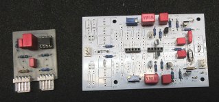
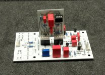
As has already been criticized several times, the input capacity of the circuit with the BJTs connected in parallel can be too high for some MM cartridges. I experimentally built the circuit with just one input pair using the existing PCB, that works too. But I don't have any pickups that are critical in terms of capacity, so I can't say if that means an improvement for those.
In addition, I was able to modify the existing circuit board quite easily in order to attach a DC servo.
In the meantime, I've been working a bit on the Supra / SLN circuit as posted from #157.
As has already been criticized several times, the input capacity of the circuit with the BJTs connected in parallel can be too high for some MM cartridges. I experimentally built the circuit with just one input pair using the existing PCB, that works too. But I don't have any pickups that are critical in terms of capacity, so I can't say if that means an improvement for those.
In addition, I was able to modify the existing circuit board quite easily in order to attach a DC servo.
Attachments
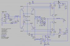
Nice scheme with very fast compound output. RIAA filter in active variable is not so good like two stages and passive filter between. Should be OP97 much better choise for servo.
In the meantime, I've been working a bit on the Supra / SLN circuit as posted from #157.
As has already been criticized several times, the input capacity of the circuit with the BJTs connected in parallel can be too high for some MM cartridges. I experimentally built the circuit with just one input pair using the existing PCB, that works too. But I don't have any pickups that are critical in terms of capacity, so I can't say if that means an improvement for those.
In addition, I was able to modify the existing circuit board quite easily in order to attach a DC servo.
By capacity you mean capacitance?
What cartridges did you use the preamp with?
Can you upload the asc file so I can compare it with mine?
One thing that I did try was increasing the voltage to +/-30v, and the results were superb. I'm not sure you can use the 550/560, because I think voltage is too close to their maximum.
Another thing to consider is using THAT complementary transistor chips, which can be a good option.
Have you tried the SLB with and without the DC servo?
Can you fill in with some facts, please? Which cartridges will be influenced of the input capacitance?As has already been criticized several times, the input capacity of the circuit with the BJTs connected in parallel can be too high for some MM cartridges....
This is an ELEKTOR design from 1982. The input capacitance was specified at 250 pF.
Best regards!
Best regards!
You will have to prepare voltage reductor for servo if you insist in higher common voltage, nonsense. If you measure transistor transition speed is current on first pair main factor, not increased voltage. I think 1mA is optimal. In any case, you have enough headroom for any kind input signal with +-15V. I already made own scheme and RIAA preamplifier with current feedback topology and have on output 20mA (BD139/140) in purpose of following stages with lower impedance to get perfect undisturbed sound.
Is that really true?This is an ELEKTOR design from 1982. The input capacitance was specified at 250 pF.
Best regards!
There are eight transistors in parallel
8 x 3.5 pF + 8 x 6 pF = 76 pF with a rough estimate
- Home
- Source & Line
- Analogue Source
- BC550 BC560 Very low noise RIAA