Looking really good Eric.
Another newb question please - are those tantalums the only resistors in the signal path?
Thanks, Haden
Another newb question please - are those tantalums the only resistors in the signal path?
Thanks, Haden
Great work Eric! I will do the same CCS except using the UBiB v1.3.Nice work, WKCox! <snip>
I'm interested to know why you (and otheres I see) connect all of the RCA input gronds together and then link them to the output ground.
I was going to ask about the resistor but someone beat me to it 🙂
I was going to ask about the resistor but someone beat me to it 🙂
question to WKCox #1396
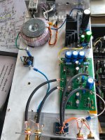
Hello WKCox, is that a vibration dampening mat on your case floor? (I used that a lot in my 'extreme' car hifi days years ago) Against microphonic influences / vibrations? Greets Dirk
Hello WKCox, is that a vibration dampening mat on your case floor? (I used that a lot in my 'extreme' car hifi days years ago) Against microphonic influences / vibrations? Greets Dirk
Hello WKCox,
is that a vibration dampening mat on your case floor?
(I used that a lot in my 'extreme' car hifi days years ago)
Against microphonic influences / vibrations?
Greets Dirk
Exactly! The steel panels of the enclosure ring like a bell. I bought some damping material from a local autosound store and applied to the bottom and top panels -- very effective in squelching the vibration. It's also very heavy which gives added mass to the total enclosure helping to reduce vibration and microphonics.
I'm interested to know why you (and otheres I see) connect all of the RCA input gronds together and then link them to the output ground.
I was going to ask about the resistor but someone beat me to it 🙂
From past experience, common ground seems to work best in most cases, reducing the possibility of ground loops. I was considering running all input grounds to the selector switch, since it's built to switch both signal and grounds, but decided against it, knowing that would result in switching transients (clicks and pops). Suggest experimentation to find the best approach in any given situation.
The board has arrived today! Many thanks to qwertyl and all other that involved. Mr. Nelson Pass, THANKS!
Besides the 3W PSU resistors, are 0.25W Resistors also ok? Might wanna stuff some with spare Takman 0.25 Watters...
Pass DIY Addict
Joined 2000
Paid Member
Another newb question please - are those tantalums the only resistors in the signal path?
The 1K gate resistors and the 100R output resistors next to the 10uF caps are the ones that are most "directly" in the signal path. Someone will probably correct me here, saying that the resistors to ground are also part of the signal path. Since the gate resistors are mostly there for stability, it is my understanding that their specific values are not critical. Since the signal will be smaller following the volume pot, I used smaller value 620R there and 1K values following the nutube. I didn't have any tantalums that are close to 100R for the outputs. Don't know that I'll actually hear a difference with them, but I had a few laying around from years ago, so I used them here.
WKCox: I was wondering what that was on the bottom of your chassis. That's an interesting idea to add some mass to an otherwise lightweight chassis and keep it from ringing all at the same time!
I haven't measured the bias current through the 475R, but my voltage at T5 and T6 seems to be running 0.1v higher than spec, as is my voltage following the Zener at T4. I presume this isn't much to worry about or adjust?
Last edited:
Thanks Eric
Helpful, thanks. I'm determined to understand what the circuit is doing before I build it. Starting from a very rudimentary level of knowledge.
The 1K gate resistors and the 100R output resistors next to the 10uF caps are the ones that are most "directly" in the signal path. Someone will probably correct me here, saying that the resistors to ground are also part of the signal path. Since the gate resistors are mostly there for stability, it is my understanding that their specific values are not critical. Since the signal will be smaller following the volume pot, I used smaller value 620R there and 1K values following the nutube. I didn't have any tantalums that are close to 100R for the outputs. Don't know that I'll actually hear a difference with them, but I had a few laying around from years ago, so I used them here.
Helpful, thanks. I'm determined to understand what the circuit is doing before I build it. Starting from a very rudimentary level of knowledge.
'Ringing'
I was intrigued after reading through a review of the Nu-Tekt (Nu-Tube) headphone amp where it is stated that this 'moble device in a tin can' does not suffer from any ringing!!! On further investigation via the build manual/instructions, there is a rubber and foam 'cushion / suspension' system that prevents the nu-tube from ringing via a daughter board the nu-tube is soldered too and kept clear of the mother board via this cushion system by a milimeter or two, top and bottom. Conected to the mother board by a simple looped wiring harnes.
I'll be giving this a go.... To acheive the same results I will have to lift the nu-tube and pins clear of the PCB by a few mm's (insert a rectange of sticky backed foam) and have flying leads (looped) from the nu-tube pins to the pcb corresponding holes.
Anyone tried it?
Last edited:
No not that......sorry buggered if I can clip the page from build guide and post.
It’s on the rsonline nutube headphone amp kit nu-tekt technical info.
It’s on the rsonline nutube headphone amp kit nu-tekt technical info.
Last edited:
Have my Pass B1 nutube running! It certainly deserves a nice chassis later on!
I used an ultrabib PSU I had on hand, nice 3300uf caps laying in the drawer. Lowered the two filtering resistors from 10R to 3R33 because of the shunt PSU. Bypassed the silmic II 10uf caps with mkp1837. PTF for the 1K resistors.
Used a leftover matched 2sk170 set for the output buffer, idss 8.5mA is probably just over the edge.
I have no noticeable ringing issues, it needed proper grounding to eliminate idle noise. My 9.1v zener gives 9.5v which give 0.7v on the heaters.
So overall a very very enjoyable preamp. A keeper...
The soundstage is indeed more upfront which is nice.
Thanks Nelson for your generous offer!, Qwerty for distribution!
Attachments
Last edited:
'Ringing'
I was intrigued after reading through a review of the Nu-Tekt (Nu-Tube) headphone amp where it is stated that this 'moble device in a tin can' does not suffer from any ringing!!! On further investigation via the build manual/instructions, there is a rubber and foam 'cushion / suspension' system that prevents the nu-tube from ringing via a daughter board the nu-tube is soldered too and kept clear of the mother board via this cushion system by a milimeter or two, top and bottom. Conected to the mother board by a simple looped wiring harnes.
I'll be giving this a go.... To acheive the same results I will have to lift the nu-tube and pins clear of the PCB by a few mm's (insert a rectange of sticky backed foam) and have flying leads (looped) from the nu-tube pins to the pcb corresponding holes.
Anyone tried it?
The Cayin N8 obscenely expensive portable DAP uses a nu-tube in its pre amp section (you can switch it out to just a solid state pre in the software). I seem to recall that mounts the tube with silicone 'end caps' and base to damp any vibration.

Edit: all those who have emailed me about tubes I'll be in touch over the weekend for delivery details.
Last edited:
It also seems that in this kit:
KORG NuTube Portable Amp Kit | Super Best Audio Friends
…...there is some vibration damping around the Nutube so it should be available….somewhere?
KORG NuTube Portable Amp Kit | Super Best Audio Friends
…...there is some vibration damping around the Nutube so it should be available….somewhere?
A very heavy chassis could probably solve it...….isolated with a lot of bitumen. Maybe also cover the glass of the Nutube with bitumen.
The pins of the NuTube are long enough that you could fit a sandwich of damping material under it. I looks like you could even use the foam from the box it comes in. I might try it with a slice of surgical silastic gel.
The problem I suppose is that once soldered, NuTube won't really have degrees of motion that are usually best for vibration control, so something that deals with the whole board might be necessary as well.
The problem I suppose is that once soldered, NuTube won't really have degrees of motion that are usually best for vibration control, so something that deals with the whole board might be necessary as well.
Last edited:
- Home
- Amplifiers
- Pass Labs
- B1 with Korg Triode