exact
even though the servo circuit is in parallel, it feels , even if the chip is changed
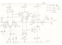
that's why I tend to avoid it, for example with a circuit like this that, if well calibrated, always has offset between 5 and 15 mv
this
Q3 and related resistances are incorrect: originally a TCR 513 was planned
even though the servo circuit is in parallel, it feels , even if the chip is changed
that's why I tend to avoid it, for example with a circuit like this that, if well calibrated, always has offset between 5 and 15 mv
this
Q3 and related resistances are incorrect: originally a TCR 513 was planned
Attachments
exact
even though the servo circuit is in parallel, it feels , even if the chip is changed
that's why I tend to avoid it, for example with a circuit like this that, if well calibrated, always has offset between 5 and 15 mv
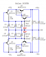
The DCG3 can have even less mV without servo, there is a trimmer, but we never know with long time passing or seasons changing or aircon etc. so better be safe than sorry. Especially when not checking from time to time. When there is input capacitor and/or DC detection for disengagement in the power amp the servo chip can be omitted of course. But its very little tonally intrusive anyway as we took much care in detailed voicing for specific chip selection. And keeps headphones safe as well. Some people use really expensive headphones with it.
I thank
I'm new in the forum and I do not know all you.
I have / want to make a pre-line section and phono level, listened what is around is not much, in fact, prices apart.
I had opted for the scheme I posted (I apologize for the OT), without capacitors and without servant, then I was intrigued by this scheme.
I take this opportunity to ask a question already posted by me in another thread:
a single j fet input differential, found that for years stuff like 5566 is OUT production,, if I select 4 and place them in parallel 2 to two, the selection could be less stringent?
would I also lower the noise figure?
as a power supply I could use that of post 2?
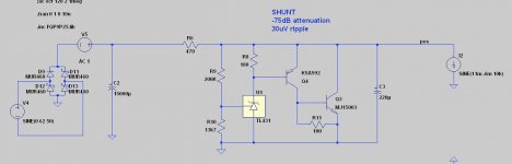
Or would it be better to have a shunt posted in another thread, always at the same signature?
I'm new in the forum and I do not know all you.
I have / want to make a pre-line section and phono level, listened what is around is not much, in fact, prices apart.
I had opted for the scheme I posted (I apologize for the OT), without capacitors and without servant, then I was intrigued by this scheme.
I take this opportunity to ask a question already posted by me in another thread:
a single j fet input differential, found that for years stuff like 5566 is OUT production,, if I select 4 and place them in parallel 2 to two, the selection could be less stringent?
would I also lower the noise figure?
as a power supply I could use that of post 2?
Or would it be better to have a shunt posted in another thread, always at the same signature?
They will lower the noise figure but they will up the input capacitance. Its also better they have alike IDSS so they will not current hog one another. Unless there is enough source degeneration resistance to each one that brings them close together for current bias.
I mean this shunt
I remember the Spectral DMC 10 Delta that put in parallel two the dual 5566 input fet in both the line and the phono
the scheme is the one I posted, except for the parallel dual fet
They will lower the noise figure but they will up the input capacitance. Its also better they have alike IDSS so they will not current hog one another. Unless there is enough source degeneration resistance to each one that brings them close together for current bias.
I remember the Spectral DMC 10 Delta that put in parallel two the dual 5566 input fet in both the line and the phono
the scheme is the one I posted, except for the parallel dual fet
Attachments
The supply in post#2 is very good for its practicality, size, dissipation, and signature. UltraBiB SSLV1.3 shunt reg usually gives more information, in the bass mainly, but you may opt to play with its electrolytic capacitors choice to match the tonality since it is a general regulator design not strictly optimized for a specific preamp etc.
I mean this shunt
TL431 is generally not super quiet, you should try and see how you like it in synergy with your application.
C2 from 33 pf, if instead I used a capacitive trimmer, I could arrange the square to perfection, even if it is a relief only instrumental
in the shunt you could to play with that 220 micro out, it was worth the trouble ?
already burned with the TL 431🙂
The supply in post#2 is very good for its practicality, size, dissipation and signature. UltraBiB SSLV1.3 shunt reg usually gives more information in the bass mainly but you may opt to play with its electrolytic capacitors choice to match the tonality since it is a general regulator design not strictly optimized for a specific preamp etc.
in the shunt you could to play with that 220 micro out, it was worth the trouble ?
TL431 is generally not super quiet, you should try and see how you like it in synergy with your application.
already burned with the TL 431🙂
C2 from 33 pf, if instead I used a capacitive trimmer, I could arrange the square to perfection, even if it is a relief only instrumental
Its about gate stopper resistors too, also not all the builders have the equipment and experience to perform such precarious compensation tweaks. Its better to be predetermined in a widely enough adopted DIY public design such as the DCG3.
in the shunt you could to play with that 220 micro out, it was worth the trouble ?
Has a limited range of M2 TO-220 compatible types due to phase margin considerations in its open loop gain analysis
the problem when approaching pre-stages are always j fet and their availability
to play with brand and model , not capacity
is it a mess to use this scheme also for RIAA semi passive phono?
Has a limited range of M2 TO-220 compatible types due to phase margin considerations in its open loop gain analysis
to play with brand and model , not capacity
is it a mess to use this scheme also for RIAA semi passive phono?
the problem when approaching pre-stages are always j fet and their availability
Search about modern & available SMD types also that can be used on mini adapter boards.
to play with brand and model , not capacity
I didn't play with brands. Its usually Vishay I used.
is it a mess to use this scheme also for RIAA semi passive phono?
Probably adaptable
not bad Nichicon muse before arriving at the folia of certain MundorfI didn't play with brands. Its usually Vishay I used.
in fact, I'm forced to look at the very good SMD, with which I'm not familiarSearch about modern & available SMD types also that can be used on mini adapter boards.
and lastly replace R1, R 6, R 7 with Texas 2575
I go OT
Could this revised and upgraded alimnentator be also the stabilized power supply of a final power stage?
Attachments
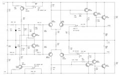
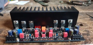
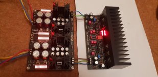
So it is running! Yay!
Spent some time getting the heatsink drilled and tapped nicely. It payed off as I have nice aligned Mosfets.
Good numbers across R10 giving me 99.5mA on each channel.
I'm not sure I'm measuring dc offset correctly. Have shorted an input (wire over +/- input) and with DMM set to Vdc I probe over line out +/-. Is this correct. I seem to get a steady 1.4v.
Attachments
- Home
- Source & Line
- Analog Line Level
- Salas DCG3 preamp (line & headphone)