Not yet. But I am measuring correctly?
You could be getting some high initial reading like that because the trimmer starts at a much higher value than its actually needed to null offset. See if it can trim it down to few mV before applying the servo chip.
or, if you want to avoid servo and / or output cap, you could calibrate the hot line stage and then leave it always on, as many do with the pre
However, it is always better to always have an offset voltage detector at the input of the final, better if set to 200 mv maximum and with optocoupler
there are also cap that are almost totally transparent, not really cheap, but .....................
a similar thing , in addition to the fuse out of the final
I know, I know that no one can stand fuse, but, changing it every now and then, I challenge anyone to realize that there is
Attachments
Twiddled the trimmers all the way anti clockwise until the voltage stopped lowering and the trimmer was clicking so I assume end of adjustment.
0.8v and 1.something v.
Any advice much appreciated
0.8v and 1.something v.
Any advice much appreciated
Last edited:
Does not sound like an ordinary preamp. Sounds like a big class A power amp.
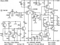
this stage line com and in scheme, how much decibel do you earn?
Twiddled the trimmers all the way anti clockwise until the voltage stopped lowering and the trimmer was clicking so I assume end of adjustment.
0.8v and 1.something v.
800 mv ?
too many
and to think of 2 resistors each in series the trimmer for a better regulation?
or you just is difficult offset control without cap / servo
and to think of 2 resistors each in series the trimmer for a better regulation?
or you just is difficult offset control without cap / servo
Shouldn't the measurements be done in operating environment (temperature) with closed enclosure lid?
Are Your Mosfets Isolated?
jimk04,
This is somehow reminiscent of a problem I encountered not long ago. Just looking at your pictures one page back, I can't see any isolators (mica, keratherm, whatever) between your mosfets and the heat sink. These have to be electrically isolated. My problem was traced to a cracked mica insulator. It appears that your mounting screws may not isolated either.
Edit:in one picture I think I see some kind of pad between your mosfets and the heatsink, do check for continuity between your mounting screws.
Use a DMM to check for continuity between adjacent mosfets and the heat sink as well.
Hope this helps.
Twiddled the trimmers all the way anti clockwise until the voltage stopped lowering and the trimmer was clicking so I assume end of adjustment.
0.8v and 1.something v.
Any advice much appreciated
jimk04,
This is somehow reminiscent of a problem I encountered not long ago. Just looking at your pictures one page back, I can't see any isolators (mica, keratherm, whatever) between your mosfets and the heat sink. These have to be electrically isolated. My problem was traced to a cracked mica insulator. It appears that your mounting screws may not isolated either.
Edit:in one picture I think I see some kind of pad between your mosfets and the heatsink, do check for continuity between your mounting screws.
Use a DMM to check for continuity between adjacent mosfets and the heat sink as well.
Hope this helps.
Last edited:
Thanks....I do have all the Mosfets isolation in place and checked with DMM before I fired up.
Yes 800mv and 1.05v
Too high a result for after tweaking the trimmers. Is it the same with non shorted inputs? Did you select Q1 Q2 for close HFE readings?
I think it was higher unshorted. I will check integrity of my shorts as it is just a loose wire in the holes but I checked for continuity over the +/- pads so I thought it had shorted.
Q1 and 2 are kit supplied items from Tea. I didn't use the other option yet.
I shall triple check things hopefully tonight.
Q1 and 2 are kit supplied items from Tea. I didn't use the other option yet.
I shall triple check things hopefully tonight.
Thanks....I do have all the Mosfets isolation in place and checked with DMM before I fired up.
Your heatsink is anodized black, thus not easily conductive on its surface. Scratch it a little for a small conductive spot at its bottom to be confident you positively verify each MOSFET's tab non conductivity to the sink with the DMM's continuity mode buzzer. It must never buzz as you go probing between the sink and each metal tab.
There was small area chipped back to bare ally that I used ....but will look again.
Thankyou all
Thankyou all
Did you install MOSFET tab holes isolation grommets? Not clearly visible in the picture. Are they grey plastic?
Yes they are in place. Black plastic. One of my pictures shows no isolation...this was just drilling and aligning Mosfets.
I will go through things later today if the wife gives me free time!
I will go through things later today if the wife gives me free time!
Just reporting back on my problem channel.
To recap both channels give 120mA measured current through the DN2540 CCS. Both channels give 5.1mA through the BF256 CCS.
The channel that also supplies the relay works fine with an offset on the output of about 20mV (without the AD823).
The other channel has an offset of 16.7V!!
I removed both BC560C's and tested them and the transistor tester said they were ok. However, I still changed them for BC327-40 with matched hfe.
I removed both the IRF9610's. Again both tested good in the transistor tester.
I replaced them anyway and then retested and I still get an offset of 16.7V. I am now at a complete loss.
Is there anything else I should check, test or change?
Thanks
Ian
IDM I hope you sort your problem. I'm sure you will.
Well I have had a bit of time. I did indeed have a shorting FET. ..but still around the 1v DC reading. However if I don't short the input. ..I can get one channel down to nearly zero and the other around 13ma. Although when I go back to measure again it seems to he different.
Have realised that one VR works opposite to the other.
Another test. All mosfet screws removed. Now both channels down to nearly 0mv.....
But without shorting the input ..do I have the correct assumption of this? ! Shorting is putting a jumper wire between +/- inputs. Because without that I seem to get nice low DC offset.
I'm buying some Nylon M3 screws. No idea how it's finding it's way around the silpad and grommet.!
But without shorting the input ..do I have the correct assumption of this? ! Shorting is putting a jumper wire between +/- inputs. Because without that I seem to get nice low DC offset.
I'm buying some Nylon M3 screws. No idea how it's finding it's way around the silpad and grommet.!
Another test. All mosfet screws removed. Now both channels down to nearly 0mv.....
But without shorting the input ..do I have the correct assumption of this? ! Shorting is putting a jumper wire between +/- inputs. Because without that I seem to get nice low DC offset.
I'm buying some Nylon M3 screws. No idea how it's finding it's way around the silpad and grommet.!
When I built my DCG3 I had a fet short that I only eliminated with nylon screws and double silpads. Somehow the fet dissipator was touching my, anodized no less, heatsink and shorting.
Never had this happen before.
- Home
- Source & Line
- Analog Line Level
- Salas DCG3 preamp (line & headphone)