It doesn't, but it is oft repeated that there is a mechanical resonance to prop up the HF of the cartridge. See attached from a Linear Audio article courtesy of Jan and S Van Raalte. I don't buy it as the HF peak is explained by too much C. Just nothing to explain the presence region dip fully.
Attachments
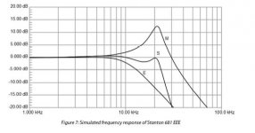
Just nothing to explain the presence region dip fully.
Non-reciprocal mechanical effects would certainly explain a difference between electrical and LP derived measurements and the fact that stylus up/down makes no difference.
Speaking of phase I just noticed that Gary Gallo speculated that a linear phase RIAA might be "unlistenable" even though many are totally happy with the FIR RIAA in many software tools. Minimum phase RIAA via FIR is easy BTW.
Last edited:
Now here is an added conundrum. Apologies for linking to a German language website but Google translate does do the job, plus its not the text I am interested in Test Audio-Technica VM740ML: die noble Art zu Horen – LowBeats
The VM740ML weighs in at 8 oz while the VM540ML is 6.4 oz. One uses a polymer housing while the other uses aluminum.
One uses a polymer housing while the other uses aluminum.
So technically mechanically they are very different. Did you mean grams?
Mechanically not THAT different as the body is the same its just the 1/2" adaptor that is plastic or metal and that can be swapped over as screwed on rather than a wipe of glue as most others use.
traditionally the 140/440 series (plastic) had a slightly different generator to the 150 series (metal)
traditionally the 140/440 series (plastic) had a slightly different generator to the 150 series (metal)
Ooops, the ounces are in parentheses.Did you mean grams?
Sorry I'm being dim now. You'll have to explain how that chart pertains to the AT meausurements as I'm lost.
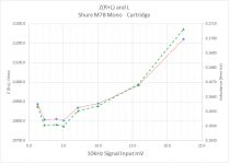
The only set of measurements I have is based upon the Shure M78 which is a mono-cartridge (two coils in parallel.)
I will run the test on a AT VM540 when I return at the end of the week.
The mid dip happens to broadly coincide with the quadrature frequency of cantilever as a transmission line. I wrote some models a time back that showed a characteristic dip in mechanical impedance, see if I can find them.
Basically, cantilevers aren't very rigid.
LD
Yes but look at the graphs on the link. Same cantilever on 540 and 740. The cheaper cartridge has the flatter response. I should have posted my 440 and 150 to George as well! Summat is odd here.
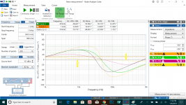
I saw some of the stuff George had posted on impedance vs signal levels. Since the Bode-100 isn't as good as the HP3577A in resolving low level signals I decided to move the test setup over to the latter and examine Z with signal from 1mV (-47dBm) to -20dBm at 10kHz. This is a first cut. I am going to have to build a jig to shield the cartridge for more precise measurement: (Jan, aren't you sorry you sold your HP3577?)
Attachments
This is a first cut.
Hi Jackini
Thanks again.
A few questions:
-First attachment, what is the division marks on the vertical axis and what does it represent (voltage level or impedance)?
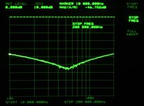
-Second attachment, what is the frequency of the test signal?
-Why do you test the two coils in series instead of testing a single coil?
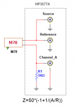
-Can you present a schematic of the test setup you are using?
I am heading to the same directionI am going to have to build a jig to shield the cartridge for more precise measurement:
George
Hi Jackini
Thanks again.
A few questions:
-First attachment, what is the division marks on the vertical axis and what does it represent (voltage level or impedance)?
The vertical axis is the dB ratio of Reference to Channel "A", it can also be linear magnitude.
-Second attachment, what is the frequency of the test signal?
10kHz
-Why do you test the two coils in series instead of testing a single coil?
that's how Shure configured the cartridge
-Can you present a schematic of the test setup you are using?
Attachments
The mid dip happens to broadly coincide with the quadrature frequency of cantilever as a transmission line. I wrote some models a time back that showed a characteristic dip in mechanical impedance, see if I can find them.
Basically, cantilevers aren't very rigid.
Cantilevers are made from some incredibly rigid materials. The compliance necessary for the response anomalies if its the cantilever would be visible. Maybe if you are using cactus needles you could get significant flexure. . . With LP's the compliance is the pivot and the vinyl and the mass of the cartridge/headshell and mounting issues.
There is a technique using an accelerometer to drive the stylus to see what is happening. Lyra among others uses it to verify performance.
I'm not sure what is to be learned from measuring the cartridge inductance in parallel with a resistor that can't be determined with a simulation. The loss pathways between the mechanical energy in and electrical energy out are huge. Loading won't alter the mechanical motion. It will alter the electrical behavior. If you draw any current the magnetic nonlinearities will get mixed in. Maybe the additional distortions are pleasant?
Jackinnj's setup could allow for quantifying the distortion contribution.
…...and so was the Tacoma Narrows bridgeCantilevers are made from some incredibly rigid materials.
")
LD
…...and so was the Tacoma Narrows bridge
LD
Ha ha.
The video of that thing falling to pieces still amazes me.
The vertical axis is the dB ratio of Reference to Channel "A", it can also be linear magnitude.
Thanks. So it is freq response rel to Reference (and it’s 10dB/div).
10kHz
Ouch. It seems that I am blind (in addition to being deaf)
that's how Shure configured the cartridge
My fault again. You've already mentioned in post #238 that the two coils are paralleled .
George
Attachments

- Status
- This old topic is closed. If you want to reopen this topic, contact a moderator using the "Report Post" button.
- Home
- Source & Line
- Analogue Source
- Cartridge dynamic behaviour