That is a pretty good test of the visual distortion. And the frequency response test in the post before it was done well too. They show the performance of that single ended circuit, and that output transformer.
Please take the time to read if you want. Those who already know this will not need to, but some who know less will learn something.
41.8 Hz shows a fair amount of 2nd Harmonic distortion . . . not real bad for that low of a frequency, typical of not enough inductance in the output transformer. Low inductance = Low impedance at low frequencies. The output tube not only has to drive the speaker, but it also has to drive the low impedance of the output transformer at low frequencies. The low inductance and consequential low inductive reactance is is characterized by the little wobble you see on the downward slope of the sine wave. Part of the wave shape (wobble) is caused by the phase of the 2nd Harmonic versus the fundamental frequency.
80.0 Hz shows the same as the 41.8 Hz screen picture, just less wobble and less 2nd Harmonic distortion. The inductive reactance is 2X at 80 Hz, versus what it is at 40 Hz.
101.5 Hz is similar to above, but again less 2nd Harmonic distortion than at lower frequencies.
199.5 Hz you are still seeing 2nd harmonic distortion, but now the inductive reactance of the output transformer is higher. The transformer impedance is higher, and now you can see the 2nd harmonic distortion of the tube (notice that the top of the sine wave is fatter than the bottom of the sine wave). The transformer inductive reactance is no longer covering over the tube’s natural (intrinsic) 2nd harmonic distortion.
319.4 Hz to 5000 Hz, you can see the tube’s natural 2nd Harmonic distortion, very small. But, you still see the fat top and narrow bottom of the sine wave (caused by the 2nd Harmonic).
20000 Hz You can see that the sine wave is visually almost perfect. That is because the 2nd Harmonic of the tube (40000 Hz) is beyond the bandwidth of the output transformer. Therefore, the 2nd harmonic 40000 Hz of the tube does not come out the output transformer.
A 10000 Hz square wave would show if there is any “ringing”, and would show the rise time of the signal.
A 1kHz square wave would show if there is any downward slope of the top (and upward slope of the bottom) of the square wave (indicating the attenuation of lower frequencies).
One more thing: It seems like the power transformer has enough laminations to power 2 output transformers. But the power transformer has to work at 50 or 60 Hz AC, and its I and E laminations are interleaved with no air gap. But the output transformer laminations seem to be 1/2 or less of the power transformer, and we might like them to go to 20Hz. The output transformer I and E laminations are not interleaved, and they have an Air Gap between them, and there is DC on the primary winding. All of that reduces the inductance and therefore the inductive reactance, and the tendency to saturate at low frequencies.
With the equipment that you have, you have done a good job of testing. If you use a larger signal, the distortion will be increased. And at 20000 Hz, the signal may be attenuated even more relative to 1000 Hz (due to high frequency slew rate limiting). But I bet nobody wants to hear music at 20000 Hz at such a high power level.
Last edited:
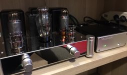
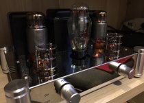
Measure the distance between the grill holes protect the lamps.
Boyuu a10 250mm x 70mm
These amps are like brothers, maybe this part will suit you.
272mm X 50mm
Oh well - no little kids with grabby hands here anyway😉

That is a pretty good test of the visual distortion. And the frequency response test in the post before it was done well too. They show the performance of that single ended circuit, and that output transformer.
.
Thank you for the very detailed information. it's very useful.
I'll do the test with square when I get the 470uF capacitors and post the results.
Cheers
Frank
Thanks for that work, Frank; it's very interesting.Frequency response Results:.
See the results in the Excel table.
I measured the Vpp of output and I used the formulas to calculate the Vrms, dBu, V dBu, Power rms and Power dBu.
I don't have a good understanding of this type of calculations (voltaes, impedance, dB, dBm,dBu, etc.., so if you could explain it more, it would help me (and perhaps other readers?). I looked online but didn't find any explanations that were very clear since there are so many variables ('Pro' and 'Consumer' levels, -10dB vs 0dB, etc..)
Why did you choose 1 v p-p for input level? Is this the input level from a CD? I'm thinking back to LongRoad's comments about input level and distortion.
Do you have any ideas about why increasing the size of the filter capacitor wold improve the high-frequency response a bit?
Thanks again for your data and scope trace pictures. I like measurements! 🙂
Does anybody have the schematic diagram for the GemTune GS-01 tube Amplifier?
GemTune GS-01 Hi-Fi Tube Amplifier with VU meter Tubes: EL34*2 + 6N8P* – GemTune Online
It uses similar tubes as the A9 and heard good reviews about it, so I'm curious to know what are the differences in the circuit.
Thanks
GemTune GS-01 Hi-Fi Tube Amplifier with VU meter Tubes: EL34*2 + 6N8P* – GemTune Online
It uses similar tubes as the A9 and heard good reviews about it, so I'm curious to know what are the differences in the circuit.
Thanks
The recent schematics in this thread still have a glaring mistake.
The Dual Triode input tube has a floating grid, pin 4. That will affect gain, distortion, etc.
The fix is to connect pin 4 to pin 1.
Whether you are using a PCB or point to point wiring, you need to check those connections.
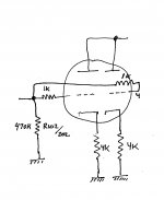
If you want to, you can use two grid stopper resistors, 1k Ohms each, one on pin 1, and one on pin 4, then tie the other ends of the grid stopper resistors to the volume control wiper that is also connected to the 470k Ohm grid resistor.
The Dual Triode input tube has a floating grid, pin 4. That will affect gain, distortion, etc.
The fix is to connect pin 4 to pin 1.
Whether you are using a PCB or point to point wiring, you need to check those connections.
If you want to, you can use two grid stopper resistors, 1k Ohms each, one on pin 1, and one on pin 4, then tie the other ends of the grid stopper resistors to the volume control wiper that is also connected to the 470k Ohm grid resistor.
If there is any tendency to oscillate, or if there is RF floating around, it reduces both of those at the input stage. Most find that they are not necessary.
I have experienced some tendency to oscillate when I had an amplifier that had the plates tied together, and the cathodes had separate self bias resistors, but they both had bypass caps, so the cathodes were also effectively tied together for AC and RF frequencies.
If you do decide to bypass the cathode resistors, it would be a good idea to install grid stoppers.
Some of the 'mod' ideas do have added cathode bypass caps.If you do decide to bypass the cathode resistors, it would be a good idea to install grid stoppers.
See below...
I'd follow the advice to put the resistor right at the tube socket (lead trimmed short), as 6A3sUMMER advises. That's actually what the 'mods' schematic below shows, but I've seen builds where the grid resistor and the grid stopper were joined together, with a wire from the junction to the tube socket.
Sometimes schematics are missing details, 'assuming' the builder will know what to do, following standard building techniques. The assumption that builders will 'know' to tie the preamp tube grids together, since the plates and cathodes are joined, is in that category. Not obvious to a beginner at all.
I put grid (and screen) stoppers on the power tubes also.
Attachments

The key purpose of having a grid stopper resistor is to isolate the control grid from stray wiring capacitance and wiring inductance. That is why all of the circuit that needs to connect to the control grid has to pass 'through' the grid stopper resistor. It is the only part that connects directly to the control grid. I use 1k Ohm grid stopper resistors on control grids.
The same can be said for the grid stopper resistor on the screen grid of pentode/beam power mode, ultra linear mode, and triode mode amps. All of the circuit that needs to connect to the screen grid has to pass 'through' the screen stopper resistor. It is the only part that connects directly to the control grid. I use 100 Ohm grid stoppers on screens.
If it works well without grid stopper resistors, leave them out. If it has problems, put them in. But what used to work may no longer work: With tube rolling; with different loudspeaker loads; and if you shift the position of wires in the amp.
The proper way to use the dual input triode in parallel is to use separate self bias cathode resistors (do not tie the cathodes together). This is true, whether or not you also add separate bypass capacitors across the separate self bias resistors. This was all discussed in the very last issue of Glass Audio, in the cover article "Paralleling Tubes Effects". If they used two 1k Ohm resistors in parallel and tied the cathodes together, then use 1k to one cathode, and another 1k to the other cathode, and do not tie the cathodes together (they will balance much better that way).
For long tailed phase splitters, that is a different story, because the cathodes do have to tie (connect) together, even if it is through a metering resistor or potentiometer.
Last edited:
The proper way to use the dual input triode in parallel is to use separate self bias cathode resistors (do not tie the cathodes together). This is true, whether or not you also add separate bypass capacitors across the separate self bias resistors. This was all discussed in the very last issue of Glass Audio, in the cover article "Paralleling Tubes Effects". If they used two 1k Ohm resistors in parallel and tied the cathodes together, then use 1k to one cathode, and another 1k to the other cathode, and do not tie the cathodes together (they will balance much better that way).
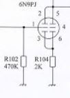
Like this?
Attachments
VictoriaGuy,
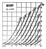
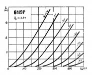
The connections are correct, but I am not real familiar with the 6N9P (seems to be like a 6SL7).
The only question is about the 75k plate resistor, and the 4k cathode resistors. Those
values seem reasonable. If the voltages are in the linear range of the 6N9P, that will work well.
The connections are correct, but I am not real familiar with the 6N9P (seems to be like a 6SL7).
The only question is about the 75k plate resistor, and the 4k cathode resistors. Those
values seem reasonable. If the voltages are in the linear range of the 6N9P, that will work well.
Like this?
Any chance you could take voltage measurements at the cathodes and anode?
Edit: Yes both cathodes please.
jeff
Last edited:
Any chance you could take voltage measurements at the cathodes and anode?
Cathodes and anode. 3 measurements if you separate the cathodes.
I'm just along for the ride here - My Chinese amp adventure was a few years ago.
I sketched the ideas that 6A3sUMMER was describing to make sure I understood correctly. (Doubling the cathode resistor, etc...)
Hopefully Frank or Greg or Navydiver will drop by with those numbers from their amps
This was what I measured a while back. Post 648
6N9P PIN 2 OR 5 ANODE 193VDC(left tube) 201 (right tube)
pin 3or6 CATHODE 2.6VDC
6N9P PIN 2 OR 5 ANODE 193VDC(left tube) 201 (right tube)
pin 3or6 CATHODE 2.6VDC
- Home
- Amplifiers
- Tubes / Valves
- Boyuu EL34 A9 Tube Amp