C11 on the display board...another 0,47uF ? Fine...
Missed that on the schematics and BOM, but yes, another 0.47u decoupling capacitor.
The headset output is there?Thx
Anyone can play dsd file for native
As I just said:
The buffer board is just a basic one without headphone amplifer (see schematics for the details). The headphone part of the display board is all in one side, actually designed to be broken of or sawed of if not needed.
Yes, it plays DSD, please see data on website or manual....
Søren - killer product, simple to use and I'm sure plenty to tweak for fun. I wanted something simple to use with my 300B headphone/pre amp.
As I just said:
The buffer board is just a basic one without headphone amplifer (see schematics for the details). The headphone part of the display board is all in one side, actually designed to be broken of or sawed of if not needed.
Yes, it plays DSD, please see data on website or manual....
I want make the built-in headphone amp , how to connect?
Hello,
I want to use a different color for the matrix led, vishay propose a variant with orange color... TDSO3150-L or the TDSO3155 could work ?
Thank you !
I want to use a different color for the matrix led, vishay propose a variant with orange color... TDSO3150-L or the TDSO3155 could work ?
Thank you !
Hello,
I want to use a different color for the matrix led, vishay propose a variant with orange color... TDSO3150-L or the TDSO3155 could work ?
Thank you !
Most standard 10mm ones should do, but check pinouts and light output.... Please note that the specified Vishay type are with selected density....
Measurements?
Soeren, I know measurements for linearity probably won't be that great since this is an R2R DAC with other benefits. I am still curious if there are measurements of say the factory complete product. Not everybody wants to use this JUST to listen to music to ...
All the best
Petter
Soeren, I know measurements for linearity probably won't be that great since this is an R2R DAC with other benefits. I am still curious if there are measurements of say the factory complete product. Not everybody wants to use this JUST to listen to music to ...
All the best
Petter
Which rs232 adapter are you guys using ? Something like this: PL2303HX Kabel FTDI USB to TTL Konverter Modul Adapter Arduino zu UART RS232 | eBay ?
I believe there are different versions ...5V...3.3V...and I did not see a power connector pon for this adapter in the manual, only tx, rx and ground, right ?
I believe there are different versions ...5V...3.3V...and I did not see a power connector pon for this adapter in the manual, only tx, rx and ground, right ?
If you have the module above at home, you can open tha case and look if there is a solderpoint/jumper to switch the voltage to 3.3 voltsWhich rs232 adapter are you guys using ? Something like this: PL2303HX Kabel FTDI USB to TTL Konverter Modul Adapter Arduino zu UART RS232 | eBay ?
Do not have any experience with the following usb-serial adapter but this one is switchable to 3.3 volt: https://www.ebay.de/itm/USB-2-0-CH340G-TTL-Konverter-Adapter-CP2102-PL2303-UART-FTDI-Arduino-5V-3-3V-/252713824136
Look into the manual (page 6)I believe there are different versions ...5V...3.3V...and I did not see a power connector pon for this adapter in the manual, only tx, rx and ground, right ?
Code:
Input Pins:
Input Voltage Low    min. -0.5V     max. 0.8V
Input Voltage High   min. 2.0V      max. 3.9 V


Output Pins:
All Digital Outputs  min. 0 V       max. 3.3V
Last edited:
Soeren, I know measurements for linearity probably won't be that great since this is an R2R DAC with other benefits. I am still curious if there are measurements of say the factory complete product. Not everybody wants to use this JUST to listen to music to ...
All the best
Petter
There are THD specs on all products on the website and in the manual. And it's something I check on all products before shipping.
I'm not sure if this has been answered anywhere else, but
What instrument was used to measure the resistors to 0.01% precision? At <<1 ohm this would (obviously) be a significant problem.
What instrument was used to measure the resistors to 0.01% precision? At <<1 ohm this would (obviously) be a significant problem.
I'm not sure if this has been answered anywhere else, but
What instrument was used to measure the resistors to 0.01% precision? At <<1 ohm this would (obviously) be a significant problem.
Ask Vishay.... But I saw a standard HP high precision multimeter used, probably controlled over IEEE488....
At <<1 ohm this would (obviously) be a significant problem.
Why particularly at <<1 ohm? How is it relevant?
Why particularly at <<1 ohm? How is it relevant?
There is a lower (voltage) noise floor. V=IR. Small form factor resistors are limited in the power they can dissipate (the current they can pass) and very likely require temperature compensation for current values that aren't representative of what the system will encounter during operation.
0.01% is 10,000
1A across a 1 mohm resistor is 1mV. 0.01% of that would be 0.1uV. You have to measure beyond 0.1uV to guarantee it doesn't round up to 0.2uV.
You could bump it up to 100A to get farther from the noise floor, but that wouldn't be encountered in operation, would probably blow the component and would definitely require temperature compensation.
The $1200 Agilent 34461A only guarantees accuracy for 100ohm and above. And the above (I believe) is the reason why.
I can't see the problem, it's not 1 mOhm resistors I'm using.... the 2r is 10 Kohm.
If I connect an encoder to the pins labeled input A/B from encoder (J4) will I be able to control digital volume by rotating the knob?
If I connect an encoder to the pins labeled input A/B from encoder (J4) will I be able to control digital volume by rotating the knob?
Yes.
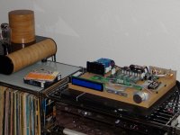
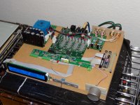
Hello together, just before Christmas I got my parts ... great, plug & play I would call that ... right away I did not like the way how the user information is displayed. Without further ado, I built an interface that displays everything in plaintext.
At the moment I am feeding the 1941 with a cd-player over the RCA input. The next step would then be to use as source a raspberry pi, but I still have to think about that. Anyway, the result is already to be described as very good, maybe I'll do something else on the power supply, that still has potential ...
After that I will make a case. I also have to think about that...🙂
Attachments
- Home
- Vendor's Bazaar
- dam1941 - Next Gen Discrete R-2R Sign Magnitude 24 bit 384 kHz DAC module