output could be taken at the primary or secondary of transformer.
Sugested stantard EI transformer
Sugested stantard EI transformer
You are reinventing Sue Parker's Zeus Amp. Read up and learn the finer points she and others have shared over the years.what do you think about the "balanced MoFo" presented here? ...
Can someone please comment on post 1662 in which a Tubecad variation is shown using an order of magnitude smaller inductor? Here is the relevant commentary from Broskie's blog entry re the circuit.
"Don't you mean 2-Henry inductor? No, 2mH is enough, as the 8-ohm load is in parallel with the MOSFET's fantastically-low output impedance. The choke's own DCR, however, is in series with its inductance, which undermines the MOSFET's low output impedance. Thus, an air-core inductor isn't the slam dunk easy option that it might seem at first, in spite of offering such benefits as no saturation and no core hysteresis. For example, a typical 2mH air-core inductor might present a DCR of 0.3 ohms, even with 16-gauge wire, four times more than an IRFP250's 0.073 ohm Rds. In other words, a larger-valued air-core inductor will be needed, say 10mH, but then it must incur a larger DCR. In addition, the inductor's DCR will create a sizable DC offset at the output; for example, 3A against 0.8 ohms creates a 2.4Vdc offset. Thus, with an air-core inductor, an output coupling capacitor will be needed, say a 1kµF/10V capacitor." Cathode-Follower Power
"Don't you mean 2-Henry inductor? No, 2mH is enough, as the 8-ohm load is in parallel with the MOSFET's fantastically-low output impedance. The choke's own DCR, however, is in series with its inductance, which undermines the MOSFET's low output impedance. Thus, an air-core inductor isn't the slam dunk easy option that it might seem at first, in spite of offering such benefits as no saturation and no core hysteresis. For example, a typical 2mH air-core inductor might present a DCR of 0.3 ohms, even with 16-gauge wire, four times more than an IRFP250's 0.073 ohm Rds. In other words, a larger-valued air-core inductor will be needed, say 10mH, but then it must incur a larger DCR. In addition, the inductor's DCR will create a sizable DC offset at the output; for example, 3A against 0.8 ohms creates a 2.4Vdc offset. Thus, with an air-core inductor, an output coupling capacitor will be needed, say a 1kµF/10V capacitor." Cathode-Follower Power
The MOAMOFO
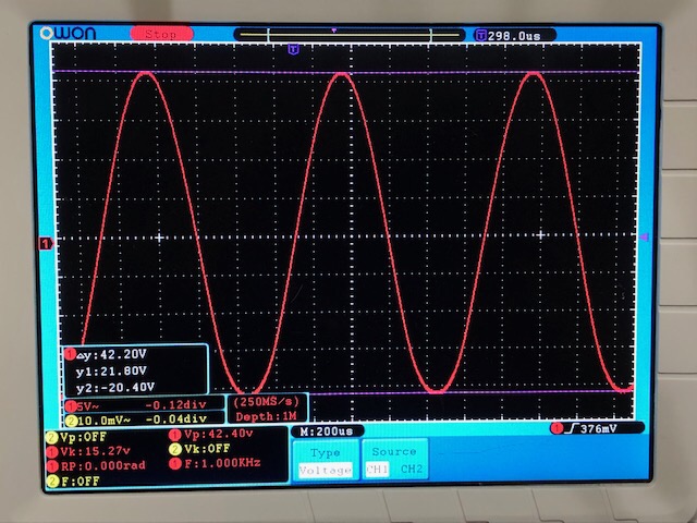
I am currently running the Mother of All MOFO’s and it’s putting an ear to ear grin on my face. 4.65 amp bias current at 37v supply rail with big fat IXYS MOSFET putting out 160w per channel, microwave oven transformer and Melbourne Preamp driving it. My Melbourne was running on +/-24.5v rails so max output was limited by Preamp at 42.4Vpp into 8ohms. I will boost preamp rails and should be able to hit 50wrms into 8ohms. Here is recent O-scope shot at onset of clipping.
Cooling is of course provided with a heatpipe CPU cooler and PWM fan. MOSFET body temp is only 50C so not even hot.
Attachments
Last edited:
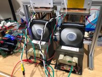
Here is how the CPU coolers are mounted to the MOSFETs. I am using ceramic spacers and heatsink compound (2x better than keratherm pads). CPU coolers are surplus Dell units with the big copper pad. I recently got these 15mm T rails from Maker Beam. Nice stuff.
Attachments
XRK971.
You are a super diyer.
Skilled in electronic and mechanical aspect . I take my hat off .
Is this the ' best ' sound to your ears ???
cheers
You are a super diyer.
Skilled in electronic and mechanical aspect . I take my hat off .
Is this the ' best ' sound to your ears ???
cheers
Thanks for the kind words KP, but it’s no big deal to use tinker toys to assemble heatsinks.
I am still assembling the cap Mx and second power trafo, will have stereo soon and will describe sound once I hear in stereo. In mono, it sounds like a MoFo for the smoothness and transparency but with the grunt of what feels like a 100w Class AB when driving a low sensitivity speaker.
I am still assembling the cap Mx and second power trafo, will have stereo soon and will describe sound once I hear in stereo. In mono, it sounds like a MoFo for the smoothness and transparency but with the grunt of what feels like a 100w Class AB when driving a low sensitivity speaker.
Last edited:

Look for TO-264 package and one that can handle about 90A and 600w. Then you know it will work fine at 160w. The IXTK88N30P is a good choice if you want to use an N channel.
Here is how the CPU coolers are mounted to the MOSFETs. I am using ceramic spacers and heatsink compound (2x better than keratherm pads). CPU coolers are surplus Dell units with the big copper pad. I recently got these 15mm T rails from Maker Beam. Nice stuff.
Very smart idea to put the CPU cooler upside down. I have ordered some Arctic F8 PWM rev.2 fan tonight. It should do the trick.
Cool built, thanks for sharing your pics, congrats!
Can someone please comment on post 1662 in which a Tubecad variation is shown using an order of magnitude smaller inductor? Here is the relevant commentary from Broskie's blog entry re the circuit.
"Don't you mean 2-Henry inductor? No, 2mH is enough, as the 8-ohm load is in parallel with the MOSFET's fantastically-low output impedance. " Cathode-Follower Power
AFAIK the reason to use a 50mH choke or bigger has to do with the power bandwidth. This choke is in parallel with the speaker so the current is divided between the choke and the speaker. If all the current gets eaten by the choke, there is nothing left for the speaker. So until a certain output everything is fine, but beyond that point the low frequencies are getting worse and worse. With a 2 mH choke, you will start losing your low frequencies really soon (at 600 Hz, you already lost 50% of the current).
If the choke has an impedance of 8 ohm, that is in parallel with a 8 ohm speaker, the current to the speaker is down to 50%.
With F= R / (2pi x L) this is calculated.
Very smart idea to put the CPU cooler upside down. I have ordered some Arctic F8 PWM rev.2 fan tonight. It should do the trick.
Cool built, thanks for sharing your pics, congrats!
I had an F8 and it’s kind of noisy. Just got a Noctua NF-A8 and OMG! You cannot telli it is on based on sound. This is with the little LNA (low noise adapter cable that comes with it limits RPM to 1750). I mean silent with ears 3in away. They did some amazing CFD tweaks to the airflow to stop sources of the noise. Very few products have blown me away quite like this one. I mean there is no comparison with any other fan I have heard. Totally worth $15ea.
Last edited:
Semi Off-topic! These fans look great, but they look like they need a modulated power input rather than a simple DC voltage. Can they be run with a DC (or AC line) voltage for simple constant speed operation?
Thanks,
Skip
Thanks,
Skip
Which F8 did you use ? The F8 PWM Rev.2 is very quiet.
V2.
The Noctua is crazy silent. I mean you will be flabbergasted at the difference. The PWM controllers that go for $5-$8 work well. Use the temp sensor function and fan speeds up if it senses too warm. Also has buzzer alarm if fan stalls or if it senses overtemp condition. Setpoints sort of adjustable via dip switches and two pots let you control min/max fan speed. I stuffed the thermistor bead in between fins.
@Skip PWM controllers here:
Automatic Temperature Control CPU Fan Speed DC Controller 12V PWM PC Board PN | eBay
Amazon.com: Diymore DC12V 5A PWM 4 Wires PC Fan Temperature Manumotive Speed Controller Module CPU High-Temperature Alarm with Buzzer and Probe for Arduino Heat Sink: Computers & Accessories
With Noctua NF-A8 MOSFET body temp is 70C at lowest (inaudible) fan speed. With temp sensor in place it brings MOSFET temp down to 50C and fin temp at 40C. Noise is audible barely at 8in.
Last edited:
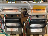
how do the microwave transformers cope with such a big current?
what model are you using?
what voltage for output cap? at least 63V?
what model are you using?
what voltage for output cap? at least 63V?
Last edited:
Microwave transformers are designed to handle large DC currents (air gapped core). I am using two 10mF 50v caps back to back for 5mF 100v rated output couplers.
I don’t have a physical model for MOT except using measured mH value and DCR from LCR.
I don’t have a physical model for MOT except using measured mH value and DCR from LCR.
Microwave transformers are designed to handle large DC currents (air gapped core). I am using two 10mF 50v caps back to back for 5mF 100v rated output couplers.
I don’t have a physical model for MOT except using measured mH value and DCR from LCR.
Are you using both the primary and secondary on the transformer?
Maybe I need to go fetch an old one before letting it go to the trash.
I have a few other microwave transformers.
- Home
- Amplifiers
- Pass Labs
- Build This MoFo!