For new readers: do you heatsink the V-FETs doing this?
that's mandatory

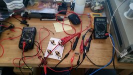
Attached you'll find the setup that I used for Vgs grading. VFets have near-zero temperature coefficient, hence the bias won't run away when the part gets hot (this also allows for the omission of a source resistor in-circuit). On the other hand, this also means that you don't really have to wait for the parameters to settle, you crank up/down the gate voltage reasonably swift, read the current/voltage, and shut the VFet off again.
Attachments
Last edited:
Feedback
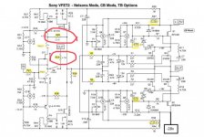
Compared to the DIY board there’s a difference in the global and cascode feedback.
R29 22.1k Cascode feedback doesn’t exist,
R23 4.75k global feedback with omitted ground, vs 2.21k and 332R to ground.
What would be the consequence of trying these two ideas?
I have searched and there’s no real answer to these ideas.
Attachments
Compared to the DIY board there’s a difference in the global and cascode feedback.
R29 22.1k Cascode feedback doesn’t exist,
R23 4.75k global feedback with omitted ground, vs 2.21k and 332R to ground.
What would be the consequence of trying these two ideas?
I have searched and there’s no real answer to these ideas.
It is the balance of front end vs global feedback.
R29 reduces the front end gain. R23 increases the output gain.
Both together lowers the total loop feedback. These are where Nelson put them for the double output version. With the single output DIY version he said it needed more feedback to get the performance he wanted. Also keep in mind that some of these changes are to make it easier for most builders to be successful.
IMHO,
The original vfet part 2 article version didn’t sound great. The values in the schematic above are what I’m running and it’s a big improvement over the original. I’m sure that’s why Nelson changed them. The DIY single pair version sounds closer to the modified double output version than to the original article version.
Hope this helps,
IMHO,
The original vfet part 2 article version didn’t sound great. The values in the schematic above are what I’m running and it’s a big improvement over the original. I’m sure that’s why Nelson changed them. The DIY single pair version sounds closer to the modified double output version than to the original article version.
So you applied more feedback, have you?
It looks to me like he reduced the front end feedback and then increase the gain so it didn’t all go to the global loop.
See Sony VFET Amplifier Part 2
See Sony VFET Amplifier Part 2
Compared to the DIY board there’s a difference in the global and cascode feedback.
R29 22.1k Cascode feedback doesn’t exist,
R23 4.75k global feedback with omitted ground, vs 2.21k and 332R to ground.
What would be the consequence of trying these two ideas?
I have searched and there’s no real answer to these ideas.
I was wrong about omitting the ground it is located @ R24 and is the same value.
So from what Ive learned R23 is global gain:
750r initially with 150r to ground behind the switch
4.75k omit 150r to ground (changed by Papa)
2.2k on DIYkit with no Cascode feedback.
Cascode feedback on Pt2
10k initially, changed to 22k
This looks like a lot less global feedback. But more than having the switch open. I like options so I am trying to understand before I let the smoke out.
Looking for a kit?
I just listed to the Swap Meet a VFET-2 Essentials kit + Supplemental kit purchased from the DIY Store in 2016. If interested, look there for details.
I just listed to the Swap Meet a VFET-2 Essentials kit + Supplemental kit purchased from the DIY Store in 2016. If interested, look there for details.
PM Sent
I just listed to the Swap Meet a VFET-2 Essentials kit + Supplemental kit purchased from the DIY Store in 2016. If interested, look there for details.
A friend of mine gifted me one of these amps a while back. I have some middle of road efficient speakers. They're the Monitor Audio Platinum PL100 II's rated at 88dB sensitivity. I absolutely love the sound of this amplifier and plan on keeping it for a long while. I'm not technical at all when it comes to amp design or building. For some albums I wish the amplifier were capable of more gain as some of the music I listen to is mastered quite a bit quieter by comparison to others. My thought was to use something like this to utilize the extra voltage the balanced XLR output of my Directstream DAC has versus the unbalanced RCA outs. If I'm not mistaken the voltage of the XLR outs it twice that of the unbalanced RCA outs. This could solve some of the issues I'm having getting certain albums to sound louder. It's using a high quality Jensen transformer and I've heard great things about Jensen transformers:
Jensen Transformers ISO-MAX PO-2XX ISO-MAX Stereo Audio Line Output Isolator 1 to 1 Ratio / Hum Eliminator, XLR/XLR
I was emailing back and forth with one of the sales guys about me potentially buying one of these with RCA outputs and he mentioned that doing this could cause distortion as this amp might not like all that input voltage. Should I be worried about this? What do you guys think about this? Are there any other high quality options out there that may better fit the bill?
Last edited:
IMHO,
The original vfet part 2 article version didn’t sound great. The values in the schematic above are what I’m running and it’s a big improvement over the original. I’m sure that’s why Nelson changed them. The DIY single pair version sounds closer to the modified double output version than to the original article version.
Hope this helps,
Botte,
Could you share your subjective opinion between the single pair and the modified double?
Thanks. Nash
Well, I would say that the double version is more dynamic/punchy and that is about it. The top end is very similar to the DIY version.
These are both exceptional amps. I have not had anyone not like either amp. The only issue is if you don't have high efficiency speakers you may run out of steam. If you are driving the OBL-15 the DIY version on the top and the F5 on the bottom should work well.
My two cents,
These are both exceptional amps. I have not had anyone not like either amp. The only issue is if you don't have high efficiency speakers you may run out of steam. If you are driving the OBL-15 the DIY version on the top and the F5 on the bottom should work well.
My two cents,
Well, I would say that the double version is more dynamic/punchy and that is about it. The top end is very similar to the DIY version.
These are both exceptional amps. I have not had anyone not like either amp. The only issue is if you don't have high efficiency speakers you may run out of steam. If you are driving the OBL-15 the DIY version on the top and the F5 on the bottom should work well.
My two cents,
Thanks Botte. Appreciate your comments.
All parts for my modified double build are now purchased and have the cases almost complete but unfortunately down with the flu. Plus traveling for two months soon so these wont be ready till April.
Yes, I am planning on driving the mid/tweeter sections of the OBL15 with the Vfets and the bass with my F5TV3.
nash
Happy New Year to all.
Just got back to using the VFET2
From my last post Changed C1,C2 to 220uF and C3,C4 to 50uF (2 100uF in series) as suggested and didn't hear a putt putt (1 beat per second low frequency}
usingTea Bag boards and Botte changes
Now I have a problem in one of my channels (call it Channel A) . I turn on the power and bias current is about 2A and DC offset is 600mV. I can lower bias and offset by trimming P1, P3 and P4 - P2 seemingly doesn't have any effect. After an hour or so of tweaking I have 1.25A of bias and 50mV offset. Left amp on for 3 hours - everything stable. Channel B is at 1.25A of bias and 15mv of offset. Turn off amp.
Next morning Channel B is1.25A of bias and 15mV upon turning on the power
Channel A has reverted to 2.25A bias and 550mV of offset - which I can adjust in about an hour to 1.25A and 50mV offset.
Turn off power - high current and offset return to Channel A 😕
Thoughts anyone?
Best and thanks
Bob
Just to be clear, you have to adjust the pots to reach the 1.25A/50mV again, or does it settle on its own once it's warmed up?
I would suspect a faulty pot or a weak solder joint.
I would suspect a faulty pot or a weak solder joint.
- Home
- Amplifiers
- Pass Labs
- Sony vFET Amplifier Part 2