yep, many thanks!!! but 6 weeks to manufacture... will be looking to smth similar.
Last edited:
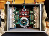
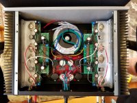
That's some really nice soldering you've got going there, BDP, neat and clean solder joints across the board!
It looks like you have 10R degeneration resistors installed in the fronted. Did you match the JFets' Idss accordingly?
Did you have the chance to compare the parallel build with the single pair diy Sony VFet amp by any chance?
It looks like you have 10R degeneration resistors installed in the fronted. Did you match the JFets' Idss accordingly?
Did you have the chance to compare the parallel build with the single pair diy Sony VFet amp by any chance?
It shows 1470 in stock, can ship immediately. Not available in Russia?
Nah, just looked over the upper line. Made an order - I am using the proxy mailbox in Oregon.
thanks again.
That's some really nice soldering you've got going there, BDP, neat and clean solder joints across the board!
It looks like you have 10R degeneration resistors installed in the fronted. Did you match the JFets' Idss accordingly?
Did you have the chance to compare the parallel build with the single pair diy Sony VFet amp by any chance?
Thank you
The jfets I had were Idss of 9ma so with the 10 ohm source resistors they are running close to 7ma. This also gives me the option to install a pot. across the source resistors.
I built the Sony VFET part 1, but I had to use the VFETS for this build. So no direct comparison.
I'm using the cascode feedback, 22K. The global feedback of 2.2K. The open loop gain was 24 dB. Closed loop of 15 dB.
The Sony VFet Vgs mismatch of 0.4 volts resulted in a current difference of 200 ma so one of the parallel outputs is running 400 ma while the other is running 600 ma. The other pairs are better matched.
Need to finish up and listen on the main system. It's always fun when you first hook up a new piece of equipment you have built!
BDP
Last edited:
Botte
Reduced cap across R20 from 470 to 220 as you suggested.
Putt-putt continues.
Will change out TL 431s in the next few days
Thanks again
Bob
Reduced cap across R20 from 470 to 220 as you suggested.
Putt-putt continues.
Will change out TL 431s in the next few days
Thanks again
Bob
Botte
Reduced cap across R20 from 470 to 220 as you suggested.
Oh I was talking about C1 and C2. Some of the TL431's are not stable with 470uF across them.
hope this helps...
I completed my build with some value modifications provided by NP here: Sony VFET Amplifier Part 2 . The front-end is biased to 1.8V. The C1 and C2 are 220uF, while C3 and C4 are 47uF. I put the Zeners underneath the OS board. Thank you Nelson for this wonderful design!
Attachments
Botte and vvs07
Thank you
I will make these changes before I change the TL 431s (ZM I'm not avoiding your suggestions. Its just easier for me to change caps than 431s
Best
Bob
Thank you
I will make these changes before I change the TL 431s (ZM I'm not avoiding your suggestions. Its just easier for me to change caps than 431s
Best
Bob
that's good suggestion , I believe already tried and worked
of course that I forgot reading about that , but now it seems familiar
I had same issues (servicing some drek ) , with oscillating TL431 , which I solved in some cases changing chip itself or , in some cases , also needing lower impedance of setting resistors
putputput

of course that I forgot reading about that , but now it seems familiar
I had same issues (servicing some drek ) , with oscillating TL431 , which I solved in some cases changing chip itself or , in some cases , also needing lower impedance of setting resistors
putputput
Just curious, flocchini, what kind of TL431 have you got?
"A" type for the TL431 should be the correct type. From GB Pass SONY VFET Version 2 - AL Boards by Tea-Bag on recommended parts:
"TL431ACLPR - Buy extra, if something will short, it will likely be these that die. The TL431B were found not to work wellI. Use "A" type."
"A" type for the TL431 should be the correct type. From GB Pass SONY VFET Version 2 - AL Boards by Tea-Bag on recommended parts:
"TL431ACLPR - Buy extra, if something will short, it will likely be these that die. The TL431B were found not to work wellI. Use "A" type."
Oh I was talking about C1 and C2. Some of the TL431's are not stable with 470uF across them.
hope this helps...
Botte, I was just about to order parts for my Vfet Al build when I saw this.
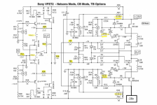
Should I switch C1, C2 to 220uf and C3, C4 to 47uf? What about C5, C6, C7, C8 and C11, C12.
Z1,Z5,Z2,Z6 zener positions are not on the PCB output board but show on the schematic below, which is from TeaBag's blog. Are these not needed?
Please advice on any resistor value or other changes.
Thanks.
Nash
Attachments
Botte, I was just about to order parts for my Vfet Al build when I saw this.
Should I switch C1, C2 to 220uf and C3, C4 to 47uf? What about C5, C6, C7, C8 and C11, C12.
Z1,Z5,Z2,Z6 zener positions are not on the PCB output board but show on the schematic below, which is from TeaBag's blog. Are these not needed?
Please advice on any resistor value or other changes.
Thanks.
Nash
I'm running the 470uF for C1 and C2 but as we were building we found some TL431's were not stable with 470uF so we replaced them, this is the A version Vs B.
That being said if you keep C1 and C2 at 220 and change C3, C4 to 47uF you get the same effect. That is bringing up the bias before the main supply voltage. If I was building a new unit that is what I would do.
My two cents...
Thank you
The jfets I had were Idss of 9ma so with the 10 ohm source resistors they are running close to 7ma. This also gives me the option to install a pot. across the source resistors.
I built the Sony VFET part 1, but I had to use the VFETS for this build. So no direct comparison.
I'm using the cascode feedback, 22K. The global feedback of 2.2K. The open loop gain was 24 dB. Closed loop of 15 dB.
The Sony VFet Vgs mismatch of 0.4 volts resulted in a current difference of 200 ma so one of the parallel outputs is running 400 ma while the other is running 600 ma. The other pairs are better matched.
Need to finish up and listen on the main system. It's always fun when you first hook up a new piece of equipment you have built!
BDP
Any reason you have omitted C7,C8?
Thanks.
Nash
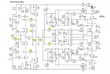
Here's more readable schematic.
In my first point to point version I used all the zeners. I don't have them in the current version. no problems. YMMV
I do have the boot strap caps installed C7 and C8.
I have C5 and C6 at 220uF. Looks like Nelson changed them to 47uF in the DIY Audio version. The RC of 47K and 220uF is low, so whatever.
C11 and C12 are just filters for the front end to keep it quiet. 220uF has been fine.
Hope this helps,
Thanks Botte. Your response helps to clear up things. Mine is a new build so I will go with C1,C2 at 220uf and C3,C4 at 47uf, all the rest 220uf.
I realize that we all have different brand preferences for caps. What brand here seems to have worked best for you? Also what voltage should these be? Bypass or not since the board has provision for it?
Nash
- Home
- Amplifiers
- Pass Labs
- Sony vFET Amplifier Part 2