I may not completely understand everything said here. I have the opinion that JN feels that since distortion generated by loudspeakers also generates a corresponding voltage that, if utilized properly, can be used to lower the distortion in the loudspeaker. Do I have this right? Now, we know that loudspeakers do behave as microphones, but there is quite a loss in amplitude compared to the original drive signal. It may have to be equalized as well. Now, does taking the feedback from a separate voice coil give a significant advantage that there is actual distortion reduction? It would seem that Demian or PMA should just measure it and see. That is all there is to is it?
What am I missing?
What am I missing?
jneutron, I think you should add centroid to that terminology list. I have the impression that you mean something more complex than the current path inside the conductor when averaged over the cross sectional area to a single point.
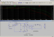
I just threw together the DVC circuit. It is not unstable, but it has ringing which needs to be cured with C1/R7. This compensation reduces the accuracy of the DVC subtraction which is shown in the yellow and green lines (ideally Vfb=Vreal). To reduce this error a faster amp is needed, since correcting inductance requires increasing feedback at higher frequencies.
I just threw together the DVC circuit. It is not unstable, but it has ringing which needs to be cured with C1/R7. This compensation reduces the accuracy of the DVC subtraction which is shown in the yellow and green lines (ideally Vfb=Vreal). To reduce this error a faster amp is needed, since correcting inductance requires increasing feedback at higher frequencies.
Attachments
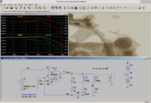
Yes K, you added a hi frequency bypass to keep the feedback loop stable, good idea. BUT does this circuit LOWER measured speaker distortion usefully?
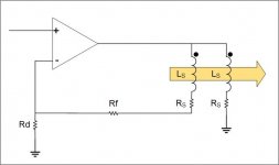
If you look at keantoken's model, note the first inductor it is fully coupled to the drive coil. It is not a microphone, but a duplicate of the reactive component of the loudspeaker. Not only a duplicate of the drive signal into an inductor, but a duplicate of all the non linearities of that reactance.I may not completely understand everything said here. I have the opinion that JN feels that since distortion generated by loudspeakers also generates a corresponding voltage that, if utilized properly, can be used to lower the distortion in the loudspeaker. Do I have this right? Now, we know that loudspeakers do behave as microphones, but there is quite a loss in amplitude compared to the original drive signal. It may have to be equalized as well. Now, does taking the feedback from a separate voice coil give a significant advantage that there is actual distortion reduction? It would seem that Demian or PMA should just measure it and see. That is all there is to is it?
What am I missing?
If you look at Demian's plot of acoustic vs difference H2 and H3, note that the diff fb spectra is very close to the acoustic in terms of level, and especially in terms of relative levels of 40, 80, and 120 amplitude..
jneutron, I think you should add centroid to that terminology list. I have the impression that you mean something more complex than the current path inside the conductor when averaged over the cross sectional area to a single point.
I just threw together the DVC circuit. It is not unstable, but it has ringing which needs to be cured with C1/R7. This compensation reduces the accuracy of the DVC subtraction which is shown in the yellow and green lines (ideally Vfb=Vreal). To reduce this error a faster amp is needed, since correcting inductance requires increasing feedback at higher frequencies.
You are correct in what a current centroid is defined as. For a solenoid coil, as frequency goes up, the current will move inward, so the inductance will go down. This is shown in my gallery, the measurements of inductors vs frequency where the inductance starts to go down with frequency. Also, as the centroid goes in, the current gets confined to less copper so the resistance goes up. Also, I show how a conductive surface near generates eddies, and that increases the resistive loss as well as reduces the inductance by exclusion. That should also occur in the gap, shorting rings, front plate and pole surfaces..But unknown is the level of effect.
The power supply guys I work with run their supplies in current mode, and I recall they have to compensate the amplifier for the load parameters. I was thinking this could happen with this feedback, but wasn't sure. That is why I said earlier, I hope it doesn't oscillate. But I'm going to ping them as to how they do the compensation.
As to faster amp, I'm not sure, the distortions in the reactive voltage shouldn't be very fast, out a few harmonics.
Once we have a better handle on what this fb type does, it may be that it can be used as an adder to a current drive amplifier to make that even better...a hybrid so to speak.
jn
Last edited:
Yes K, you added a hi frequency bypass to keep the feedback loop stable, good idea. BUT does this circuit LOWER measured speaker distortion usefully?
Unless jneutron is right and there is some useful difference between the coil EMFs, I don't think so. It will not really be any different from pure current drive, just with extra complexity and more that can go wrong. I was mainly just trying to get the simulation off the ground after PMA mentioned problems with stability.
The stability problems with this circuit are analogous to current drive, the amp's GBW limit imposes similar limits on both circuits.
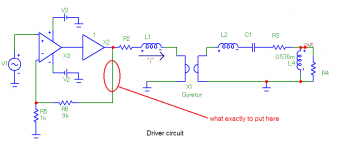
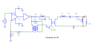
Jn, this is your compensation idea, right? It is difficult to keep the line, sometimes.
Edit: I have added a speaker scheme and am asking what you wish to put into feedback (ellipse).
Edit: I have added a speaker scheme and am asking what you wish to put into feedback (ellipse).
Attachments
Last edited:
The gyrator has 2 inputs, the second input would be on that line. L1 represents leakage inductance, which would be very small with a bifilar wound coil, so it should be very low, maybe 0.2% of Le.
Unless jneutron is right and there is some useful difference between the coil EMFs,
Actually, my thinking is that there is no difference between the coil EMF's. (for the most part)
jn
Jn, this is your compensation idea, right? It is difficult to keep the line, sometimes.
Edit: I have added a speaker scheme and am asking what you wish to put into feedback (ellipse).
That is my scheme.
As to your question, I do not know. I am not as good as you guys with this simulation.
I will think on it, but I still have much to learn with respect to what your doing.
jn
The small problem is that the "gyrator input voltage" (or EMF, back EMF) is in fact a part of JN's oversimplified Rs + Ls scheme and also a part of second coil voltage. It cannot be separated. It is an electro-acoustical transducer, not a coil with series resistance.
That excludes the transducer EMF from subtraction, only subtracting the coil flux which does not couple to the motor. You have separated things which cannot be separated.
Use 2 gyrators, put the gyrator outputs in series. Then each input is an input coil which has it's own series resistance and small leakage inductance. There is not issue as you describe.
The flux that is not coupled to the motor can be represented by coupled inductors in series with the inputs, as the voicecoils are coupled more to each other than to the motor.
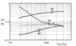
They are typical when measured with a proper microphone - you haven't missed anything. The 2nd harmonic on voltage drive is usually dominated by L(x) nonlinearity and therefore has a decreasing trend with frequency. The 3rd harmonic instead is usually dominated by L(i) nonlinearity, which increases with the inductive impedance and hence also with frequency. Figure below shows the harmonics measured in the current of a voltage-driven 6.5-in midwoofer (Peerless). (The gray lines are taken with blocked voicecoil.) Corresponding acoustic distortions are always higher than those in the current because of the baffle step and cone horn effects. Near the surround dip frequency, distortion often has a bump due to mechanical reasons.indra1 said:Esa,
it seems atypical that 3rd harmonic distortion increase while 2nd decrease at higher frequency on voltage drive as shown on your link for both woofer and midrange. Did I miss something?
See also these.
Good point, and I have done this check at the driver terminals with the cable used. No problem there.PMA said:I think it is worthy to display or at least to check distortion at the power amplifier output, with speaker connected. It is good to know that amplifier distortion does not rise with frequency and that the amplifier distortion is always at least 20dB below measured speaker distortion, everywhere, at any frequency and amplitude.
Attachments
The circular currents of the plate, since it is a shorted one turn secondary will indeed store energy, that will return as well during collapse and both coils see it.
Eddies in the plate, no. No return. They add, but do not alter the single turn currents nor stored energy.
The eddies dissipate energy and fight change of flux, causing a lowering of the dynamic inductance.
Jn
Circular currents of the plate and eddy currents in the plate are one and the same.
Eddy currents are the circular (better: circulating) currents
When alternating current is passed through the speaker’s driving coil, a magnetic field is generated in and around the coil. The probe's changing magnetic field generates current flow in the conductive material in close proximity to the coil. The induced current flows in closed loops in planes perpendicular to the magnetic flux. These current flow loops are named eddy currents (because they are thought to resemble the eddy currents that can be seen swirling in running water).
Now, the eddy currents produce their own magnetic fields that interact (tend to oppose) with the primary magnetic field of the coil (Lenz's law)
This changes the impedance of the driving coil.
Impedance
The degree of resistance and inductive reactance change of the driving coil depends on surrounding conductive material’s attributes, namely:
The electrical conductivity and magnetic permeability of the material, and the geometry of the material (i.e. , the amount of material cutting through the coils magnetic field and whether it contains edges or cuts.)
The distance that the coil is from the conductive material affects the mutual-inductance of the circuits.
If an impedance measuring system is connected with the coil and the system is balanced with the coil in air and then placed close to a piece of non ferromagnetic electrically conducting material, the resistive component R will increase (eddy currents are being generated in the electr. conductive material and this takes energy away from the coil, which shows up as resistance) and the inductive reactance Xl of the coil decreases (the magnetic field created by the eddy currents opposes the coil's magnetic field and the net effect is a weaker magnetic field to produce inductance).
If a slit or edge is present in the material, fewer eddy currents will be able to form and the resistance will go back down and the inductive reactance will go back up.
Changes in conductivity will cause the eddy current signal to change in a particular way as well as test frequency and probe diameter.
When a probe is placed close to a ferromagnetic material such as steel, eddy currents form, again taking energy away from the coil, which shows up as an increase in the coils resistance. And the eddy currents generate their own magnetic field that again opposes the coils magnetic field.
However, the inductive reactance increases.
This is because the magnetic permeability of the steel concentrates the coil's magnetic field. This increase in the magnetic field strength completely overshadows the magnetic field of the eddy currents. (remember that for metals, conductivity change spans from 0 to 110 in IACS scale, while rel permeability spans from ~1 to tens of thousands).
The presence of a slit or edge, change in the electrical conductivity of the material, change of test frequency and change in probe diameter will produce a change in the eddy current signal similar to that seen with non ferromagnetic material.
Ah, Perhaps that is the problem of understanding. Eddy currents dissipate energy as heat, and they fight dB/dt by the creation of a counter magnetic field which works to try and exclude flux change within the conductive surface. The difference is, when the stimulus ends, the eddy collapse does not return magnetically stored energy to the system like an inductor. So, it does not change the flux in a way the pickup coil can see.
Eddy currents do store energy and give it back. Otherwise it’s effects wouldn’t have been utilized.
Only please note the great difference between M1 and M2
M1 is the mutual inductance btn the excitation field and the metal mass, M2 is the mutual inductance btn the reaction magnetic field and the coil
See Fig 4, eq. (6) & (7) in second attachment
M1=kL0 and M2=kL1 where L1<<L0
This is translated in practice (coil to metal mass), to a difference in amplitude btn the excitation and the reaction magnetic field of somewhere between 100dB and 200dB
If the metal mass had greater inductance (say formed as a coil), eddy collapse would return magnetically stored energy to the system 'en masse' 😀
George
Attachments


That excludes the transducer EMF from subtraction, only subtracting the coil flux which does not couple to the motor. You have separated things which cannot be separated.
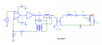
That's why I have done it. I have explained in the one previous post it cannot be separated. In fact the scheme, according to JN's hint, would go like now attached, and it does not work.
Attachments
JN, gpapag, keantoken, PMA, kstr, (et al.) sharing your immense knowledge, I realise again why I come here. Thrilling - thanks!!
//
//
You may have figured out what jneutron is seeing in his head, I wasn't able to.
Here is my schematic which AFAIK shows how it actually works. You can expand the mechanical side to include Bl modulation, suspension nonlinearity, etc.
Here is my schematic which AFAIK shows how it actually works. You can expand the mechanical side to include Bl modulation, suspension nonlinearity, etc.
Attachments
Yes, I'm hoping some is seeping in between my ears by osmosis. Even if it has little practical value in the end, it's a worthwhile exercise and things are being learned all round. Nice one folksJN, gpapag, keantoken, PMA, kstr, (et al.) sharing your immense knowledge, I realise again why I come here. Thrilling - thanks!!
//
The gyrator has 2 inputs, the second input would be on that line. L1 represents leakage inductance, which would be very small with a bifilar wound coil, so it should be very low, maybe 0.2% of Le.
L1 represents coil’s inductance (Le)
I just threw together the DVC circuit
Thanks for that.
Is the cored inductor model non linear?
If yes, can you share it?
George
- Status
- Not open for further replies.
- Home
- Member Areas
- The Lounge
- John Curl's Blowtorch preamplifier part III