
By the way, looks like I use the same transformers. See temperatures: 55 degrees the transformer, 17 degrees surrounding. 38 degrees temperature raise only. But I have bolts insulated, and nuts between the transformer and the chassis, for an air flow, and tubes draw only 65 mA each.
Attachments

Last edited:
Hi all
Well underway in my Boyuu A9 build and have some questions on mounting the RCA and Banana plug hardware. Thought it would be easier to ask verbally than type it all out and fumble it. So here goes with my questions via YouTube: YouTube
Follow up to my last (Click link Youtube that follows): YouTube
Well underway in my Boyuu A9 build and have some questions on mounting the RCA and Banana plug hardware. Thought it would be easier to ask verbally than type it all out and fumble it. So here goes with my questions via YouTube: YouTube
Follow up to my last (Click link Youtube that follows): YouTube
Hi all Well underway in my Boyuu A9 build and have some questions on mounting the RCA and Banana plug hardware. Thought it would be easier to ask verbally than type it all out and fumble it. So here goes with my questions via YouTube: YouTube
Tim- It will be interesting to see how many diyaudio readers watch your YouTube videos. I think it's more common here to type your question (since you expect typed answers!) and take photos which you can post here. Then the pictures are held on the diyaudio server for future users to view.
I think some folks here are still on low speed internet connections with data limits, and won't be keen on watching online videos, but this may no longer be the case in 2018. Personally, I find watching handheld phone videos to be a bit tiring. An adapter to use a tripod gives a steadier image.
If you check the 'washers' that came with your RCA and speaker jacks, I think you will find a pair of plastic collar washers which should sandwich the chassis between them, isolating the jack from the chassis. You want to control where the circuit grounds attach, using the lugs which are bolted to the jack body, and then using wiring to lead that ground to the appropriate 'tie-point'.
The input selector switch usually is switching only the signal wires. It looks like the little PCB has a ground plane to make it easier to attach the shields on the input wiring. You may find some of those connections are better made before bolting down the PCB. EDIT: BTW, I think you won't need the separate solder lugs on the input jacks as the metal nut will contact the ground plane on that PCB.
The 3-hole pieces of PCB board material are some sort of insulators for the speaker jacks?
BTW, the '0 ohm' black speaker jacks are the 'common' or 'negative' terminals, so you'll connect your speakers to the 0&4 ohm jacks for 4 ohm speakers, 0&8 for ...you get the idea.
Well underway in my Boyuu A9 build
Quite a bit of progress so far....
There are different styles of doing heater/filament wiring, but the two most common ones are : a)do the heater wiring first and lay it right down on the chassis with the 'signal' wiring 'up in the air' or, less commonly: b)do the heater wiring last and have it 'up in the air' with the rest of the wiring closer to the chassis.
Have you read this thread? Heater Wiring - the Good the Bad and the Ugly
Also, check that power resistor - it's not clear which terminal(s) it's supposed to be contacting from the shot in the video. Bend the leads to position it where you want it. If there's any concern, putting 'spaghetti' tubing or heat shrink on the lead can insulate it from accidental contact. Insulation stripped from wire can be used as 'spaghetti'. BTW, the springy stranded wire that came with my Chinese kit was difficult to route to where I wanted it in the chassis, so I recall using some better quality solid core wire. Hoffman amps is a good source for wire. Push back wire (like in older amps) is really nice to work with....
Attachments
Just for interest - here's a pic of the AC power and heater wiring on my Chinese amp kit -which was P2P without PCBs, so a bit different.
Actually, it might have been better to have the heater wiring take 'a shorter route' rather than all around the side, but it worked out OK and the amp is quiet.
")
For long replies, I often compose/save in Notepad or Word, and then paste in the answer in the reply box here.
BTW, I've never had any problems with private messages here at diyaudio, and it's prevented some embarrassing situations where a helpful person sent me 'corrections' via private message rather than posting it for everybody to see! I was grateful!
Actually, it might have been better to have the heater wiring take 'a shorter route' rather than all around the side, but it worked out OK and the amp is quiet.
" I feel your pain" ...Spent twenty minutes typing out reply and the server glitched and all was lost - very frustrating typing. Gotta take a break
For long replies, I often compose/save in Notepad or Word, and then paste in the answer in the reply box here.
BTW, I've never had any problems with private messages here at diyaudio, and it's prevented some embarrassing situations where a helpful person sent me 'corrections' via private message rather than posting it for everybody to see! I was grateful!
Attachments
Will rewire the heater cables and coil them up out of the way as best I can. Was finding that the wires coming from all the transformers is cheap Chinese crap with poor quality insulation. I fear I won't get a high density number of twists on them for fear the insulation will start to come apart. As it is I have run the 6N9P underneath the main PCB - those were not twisted so will re-do. I did not have good wire handy for the extension piece to the next 6NPN so will get solid core wire as per the article and braid that one up. Similar situation with the two EL34 tubes. I did get some twists on the 5Z3P but the insulation started to weaken and discolour so I left it alone at that point. It does get dense around the connection points at the Octal tube sockets so will work that as best I can as I do not want to heat stress the components too much...
I'd never seen braided wire until fairly recently.braid that one up. ..
It looks neat, but I don't know much about the electronic effect of braiding.
You might want to ask more expert readers whether braiding accomplishes the same goal as twisting AC wiring.
If you want a few feet of solid core wire for your project, you can send me a PM - I'm pretty sure I can find something here in my supplies to keep your project moving until you get a wire purchase from a supplier.
So far, my transformer is on its way to me.Yes, but you may get as the result 7.5V instead of 6.3
I hope he will provide the claimed 6.3 volts.
You have a very good temperature balance in the amplifier.
I'd never seen braided wire until fairly recently.
It looks neat, but I don't know much about the electronic effect of braiding.
You might want to ask more expert readers whether braiding accomplishes the same goal as twisting AC wiring.
If you want a few feet of solid core wire for your project, you can send me a PM - I'm pretty sure I can find something here in my supplies to keep your project moving until you get a wire purchase from a supplier.
I guess if one were to get super-technical about it a braid can only exist for 3 or more strands or wires as per Braid - Wikipedia. For wrapping two wires such as in combining heater wire pairings it would technically be a twist. I certainly am learning loads of new terms during this build
Thank you for the kind offer. Will have a look about the house as I have scads of stuff lying around. Pretty sure I have a few spools of solid core wires on the boat which I will be going to check on this weekend. At the current pace I may be ready to energize this sucker by the end of the weekend and ultimately see if I turn it into a molting pile of metal and bits on my work table. Plan would be to of course use the Dim bulb tester I built for the initial power up attempt. Would there be any value in plugging the unit into my Variac and plugging that into the dim bulb tester and slowly ramp up the power? I of course plan on doing a full review of all the connections with a multi-tester to try and ID any possible shorts or bad loops etc but at some point I will have to take a leap and try to energize the thing. I was thinking it might be better to ramp up the voltage incrementally with the variac and take some voltage readings with a multi-tester as I do this? My expectations are low since it I am building it stock before I plan to apply any of the Version 1.2 mods. I fully expect I will have a noisy/hummy amp at best after all this. From there I will try to dial it in as per the mods outlined here which the author has indicated worked for him: View attachment A9 Schematic Mods Rev1.2.pdf
I will of course have to order the bits from mouser or Digi-key etc as well. Have ordered an Alps Type 27 dual 100K wit PC connection board and the Lorlin RMS1035 Rotary switch called for in the plans (expect I won't see those for a month or so given the season and where they are coming from). Last question for those who have built this exact model: Where on the amp chassis are folks doing their chassis safety grounds? Are most folks just using one of the lug nuts for the Power Transformer making sure it has bare metal contact with the chassis. Need to make sure the green mains connector ground wire is plugged to the best spot
Last edited:
Also, check that power resistor - it's not clear which terminal(s) it's supposed to be contacting from the shot in the video. Bend the leads to position it where you want it. If there's any concern, putting 'spaghetti' tubing or heat shrink on the lead can insulate it from accidental contact. Insulation stripped from wire can be used as 'spaghetti'. BTW, the springy stranded wire that came with my Chinese kit was difficult to route to where I wanted it in the chassis, so I recall using some better quality solid core wire. Hoffman amps is a good source for wire. Push back wire (like in older amps) is really nice to work with....
This was one of the responses from post #525 that evaporated after I tried to "submit reply": The power resistor actually goes to a dedicated marked slot (or hole) on the adjacent PCB - all the rest I have sussed out. Not sure what you mean by the term "spaghetti"? Thanks. Tim.
Yes; agreed.
I guess if one were to get super-technical about it a braid can only exist for 3 or more strands or wires
3 (or more) wires can be twisted instead of braided; two wires can't be braided.
Pretty sure I have a few spools of solid core wires on the boat which I will be going to check on this weekend.
I hope not! I've done quite a bit of marine wiring and I don't think there's any spot that solid core wire would be used because of vibration concerns.
Anyway, the offer stands. One place to get still-good wire can be from older (pre-PCB, mostly) gear from the garbage/salvage.
Dim bulb tester is definitely a good idea, though it won't prevent all problems from damaging components.At the current pace I may be ready to energize this sucker by the end of the weekend and ultimately see if I turn it into a molting pile of metal and bits on my work table. Plan would be to of course use the Dim bulb tester I built for the initial power up attempt.
You should double-check your dim-bulb tester wiring. I watched your YouTube video about it, and I'm not sure you understand the purpose of the dim-bulb tester or how it works. You mention "the bulb will just blow if too much load is applied" which isn't the idea at all.
No harm in using the Variac for this as well as the dim bulb. Remember that with just the dim bulb tester, the voltage on your amp will be low - depending on the wattage of the bulb you select and the amp load. (Good Ohms law problem to spend a few minutes on: "Which bulb should I choose, and why?")Would there be any value in plugging the unit into my Variac and plugging that into the dim bulb tester and slowly ramp up the power? I of course plan on doing a full review of all the connections with a multi-tester to try and ID any possible shorts or bad loops etc but at some point I will have to take a leap and try to energize the thing. I was thinking it might be better to ramp up the voltage incrementally with the variac and take some voltage readings with a multi-tester as I do this?
Many people have built similar amps from the stock circuit and found them to be quiet without hum or noise. Layout and grounding would be the places I'd concentrate on first, to avoid hum before you power up. It's a lot easier to prevent problems than to unsolder and do 'fixes' later. (Been there; done that!My expectations are low since it I am building it stock before I plan to apply any of the Version 1.2 mods. I fully expect I will have a noisy/hummy amp at best after all this. From there I will try to dial it in as per the mods outlined here which the author has indicated worked for him:
)I wouldn't worry about mods at all. 'Upgraded' components like volume pots and switches may make a difference, but are not likely to be the 'cure' for any major problem you can hear when you power up.
Sorry, some wirds about schematic and tubes.
Some days ago I also bought China case Beyuu.
But I'm looking for 300B and 6C4C ( Russian analog 6B4G). I compared El34 and 6C4C, I think 6C4C is better, but it needs separeted 6,3V for heating.
If somebody have not read the Reichart's article: http://www.audiodesignguide.com/se/fleshblood.html
Russian transcription:
http://www.vestnikara.spb.ru/vestn/n5/reichert.htm
The case is good, but there is no place for inductor 3H with 10-20 Ohm, it's like power transformer in size.
Search on spaghetti insulation for tube amplifier will get you the answer- it's 'slip on' insulation that isn't heat-shrink.This was one of the responses from post #525 that evaporated after I tried to "submit reply": The power resistor actually goes to a dedicated marked slot (or hole) on the adjacent PCB - all the rest I have sussed out. Not sure what you mean by the term "spaghetti"? Thanks. Tim.
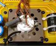
From the video, the resistor seemed to be quite close to one of the rectifier tube socket terminals. You've probably fixed that by now. I'd also make sure that the other resistor lead isn't too close to that capacitor body (even though the cap has plastic insulation), since the resistor is part of the B+ supply.
Posting some good high resolution pictures of your wiring before powering up can sometimes bring pointers from readers here, on places to double check.
I've been saved from a few mistakes by sharp eyes spotting things I'd overlooked.
Attachments
Last question for those who have built this exact model: Where on the amp chassis are folks doing their chassis safety grounds?
It sure would help beginner builders if there was a good basic 'assembly guide' included with the Chinese 'kits'.
Traditional build sequence as I was taught would have the AC input power wiring (and safety ground) as one of the very first steps, after bolting the main components in place. It can be a real 'pain' to have to 'dig down' under soldered connections to get at a connection point.
Some things just need to be learned through experience, I guess.
Even Morgan Jones 'Building Valve Amplifiers' book doesn't deal with the step-by-step process very clearly, despite the overwhelming level of detail presented.
Downloading a Heathkit assembly manual might be the easiest way to get the main ideas.
Testing and power-up
Make a pair of RCA 'shorting' plugs for the inputs for testing.
An old interconnect cable can provide the plugs - just cut the cable and solder the signal and ground (shield) together and cover with heat shrink.
Have an old (thrift store) set of speakers to connect for testing. Once the amp is quietly powering those speakers, you can remove the shorting plugs and connect up your (thrift store) CD player as a source.
It sure would help beginner builders if there was a good basic 'assembly guide' included with the Chinese 'kits'.
Traditional build sequence as I was taught would have the AC input power wiring (and safety ground) as one of the very first steps, after bolting the main components in place. It can be a real 'pain' to have to 'dig down' under soldered connections to get at a connection point.
Some things just need to be learned through experience, I guess.
Even Morgan Jones 'Building Valve Amplifiers' book doesn't deal with the step-by-step process very clearly, despite the overwhelming level of detail presented.
Downloading a Heathkit assembly manual might be the easiest way to get the main ideas.
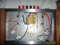
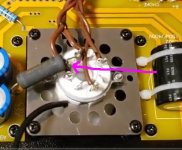
There is no doubt I would do things differently given a second go around - but this is the reason I am tackling this I guess. Just wanting to learn. Most recent image from earlier yesterday below - Still lots to clean up (from points noted today) but the two red circles are what I am thinking for chassis ground - they look fairly accessible to me without major surgery (hopefully). Look reasonable?

two red circles are what I am thinking for chassis ground - they look fairly accessible to me without major surgery (hopefully). Look reasonable?
Power transformer bolt is a pretty common spot to attach a safety ground - it's what I usually use, though I think the 'standard' requires a dedicated bolt for that purpose.
Or are you talking about where the 'circuit ground' attaches to the chassis...if at all....?
Last edited:
- Home
- Amplifiers
- Tubes / Valves
- Boyuu EL34 A9 Tube Amp