I am not a member of AES. I am not opposed to a collaborative effort however.
I do not even have a stereo setup in my house, so the chances of me listening to any improvements I discuss here is probably zero.
Jn
Thats Ok. Demian and others (myself also) have the test equipment to see the reduction.
Lots of amps laying around my place. want one?
Thx-RNMarsh
I think a label does not have enough mass to do anything much, however ime an aluminised label and my 'goop' both subtly alter noise production and consequent acoustical output...Barkhausen noise I presume, maybe.I was thinking of that stick-on label attached to the back of the magnet that you mentioned ... doing some damping.
However, if it was also a metalised piece..... what affect it would have on the magnet??
Dan.
Nezbleu, I know from subjective experience that at least some cables (standard coaxial construction) and at least some wires exhibit directional properties.I thought you believed (without evidence) that all conductors are inherently directional. So is the idea of this project to use doubled twisted pairs in each direction, so the non-existent directionality magically cancels?
Dan.
Thank you for the kind offer. I have no place for speakers.Thats Ok. Demian and others (myself also) have the test equipment to see the reduction.
Lots of amps laying around my place. want one?
Thx-RNMarsh
I have a Bose 123 sub behind my couch, but have never gotten around to actually connecting anything. Yes I know, some here would say I am lucky..😉
Life has been too hectic of late to sit around and just enjoy music. A nice cognac and good company, certainly.
Jn
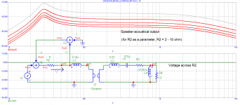
The circuit I drew is a very simple gain stage. It is designed to put the correct VOLTAGE across the resistor Rs. It does that because I am feeding back the exact reading from across that resistor to the negative feedback network.
In a single coil speaker, I do not have access to the resistive part of the coil equivalent model, I can only see the sum of the two elements Ls and Rs.
Because I am using only the voltage across the Rs as feedback, I am controlling the VOLTAGE across the resistor. And, my circuit does not care what the actual resistance Rs is as I am not measuring it.
I am not contesting this, in fact we both agree on your description. The green plot below shows that voltage across the Re is kept constant.
My question is if it would be different, in distortion reduction, from current drive. It seems to me, and the simulation is saying so, that resulting driver transfer function is same as with the current drive.
Attachments
Last edited:
My conclusion, as of now, is quite clear: "JN-drive" implements indirect current drive, just way less feasible and most likely less effective in distortion reduction (fine-print remains to be seen). We have to mod the driver (*pita*) and the amp because we will need to install degeneration also to have some electrical damping, plus proper EQ to get a reasonable SPL curve. Wrt damping, especially those cheaply built drivers with high nonlinearity are really prone to nasty "jump resonance" chaotic phenomena with no damping even if the acoustic loading is benign.
So, why not just impress the current directly rather than trying to isolate a quasi-constant resistor and relying on V/I transfer to obtain the current by impressing a voltage, with that V/I-transfer not being perfect since the isolated transfer resistance isn't perfect (if alone from thermal drift, and I'm sure we will find residuals of other distortions as well). And then use the dual VC to best extract the velocity signal with a balanced version of the servoing Birt bridge and degenerate the current drive with this (introducing an amount of MFB), rather than using the "polluted" terminal voltage.
As I've written before, real world check by impressing a current and looking at the distortion of the "JN-Drive" voltage will most likely reveal quite a bit of distortion left, coming from the transfer impedance imperfections, matching issues etc.
While it is not completely impossible that some of this distortion might cancel with other distortions that aren't addressed by current/JN-drive like BL(x), BL(i) and reluctance force, I would think the chances are nil.
Last edited:
TI and I think others already calculate the voice coil temp. They do it to protect tiny voice coils when pounding them in BT speakers. I suggested using it to compensate for power compression but they were not ready for that yet.Huh? Voltage controlled voltage drive is what I just described.
Look, the circuitry is the easy part. What pulls blank stares is the conceptual understanding of the Ls/Rs inductor model and how I am getting the voltage across the distributed Rs out.
KSTR got this immediately.
Oh, that AGC DSP function? As a first pass, I would calculate the Rs value every millisecond, and use a 30 to 50 point running average filter to calculate the Rs at thermal rates.
Knowing copper resistance rises at .343% per degree C (IIRC), the DSP can also be used to protect the coil from thermal damage by direct monitoring of the vc temperature. Imagine a display on the amp telling you the voice coil temperature in real time..with programmable limit and kill values.
Jn
And I want to add that I'm thankful John has brought up his interesting idea as it helps us all to better understand how drivers really work, with mental excercises as well as real-world experiments.
So, why not just impress the current directly rather than trying to isolate a quasi-constant resistor and relying on V/I transfer to obtain the current by impressing a voltage, with that V/I-transfer not being perfect
Yes.
And I want to add that I'm thankful John has brought up his interesting idea as it helps us all to better understand how drivers really work, with mental excercises as well as real-world experiments.
Definitely.
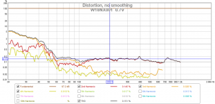
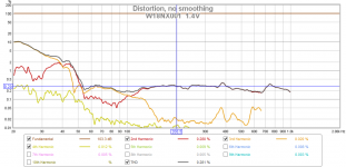
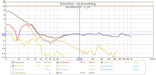
I would like to add some "real life" measurements recorded just now to show how quickly speaker distortion rises with level and also how fast is the distortion rise below resonance (as discussed earlier together with Klippel's 60% that look to be perfectly on target).
We can see linear rise of distortion with level (above resonance).
Attachments
As for fighting Rdc tempco, current drive plus Birt bridge affords that perfectly. Rdc is irrelevant for current drive anyway and the Birt bridge servoes out the DC disturbance of the velocity extraction used for degeneration (up to full MBF).
Thermal protection also is straighforward, the DC output of the brigde is a direct measure for VC temp. With a control actuator of that servo which has a stable untrimmed transfer (mutiplier would be best) the actuator control voltage can feed a soft-threshold circuit that drives a front end VCA limiter (needs some care wrt to stability/overshoot, like with any feedback system).
Thermal protection also is straighforward, the DC output of the brigde is a direct measure for VC temp. With a control actuator of that servo which has a stable untrimmed transfer (mutiplier would be best) the actuator control voltage can feed a soft-threshold circuit that drives a front end VCA limiter (needs some care wrt to stability/overshoot, like with any feedback system).
And voltage as shown is rms?... We can see linear rise of distortion with level (above resonance).
Yes, exactly.
Patel, as I think about your model, I have to ask.. Why are you not looking at the voltage across re only? That is what the circuit does.
I suspect your model is not consistent with my design. Please go back and look at my recent diagrams.
It may be easier and more accurate for you to use a 1:1 transformer to represent my pickup coil design.
Jn
Last edited:
Pavel, I see you plotted v across coil r2 as flat, I didn't notice earlier.
How do you put position dependent inductance, velocity dependent dissipation, and current slew dependent coil resistance in?
Thanks for your efforts, I am learning a lot about simulation by examining your model.
Jn
How do you put position dependent inductance, velocity dependent dissipation, and current slew dependent coil resistance in?
Thanks for your efforts, I am learning a lot about simulation by examining your model.
Jn
@Jn, How is the Voltage across Rs related to acoustic distortion and are there any mechanism other than temperature that affect nominal value of Rs?
@Jn, How is the Voltage across Rs related to acoustic distortion and are there any mechanism other than temperature that affect nominal value of Rs?
If you look at Demians plot, fourth one, it shows that the electrical voltage on the second coil has harmonics that exactly match that of the acoustic distortion.
My contention is that it is the magnetic non linearities that is causing the acoustic distortion. Since he sees the distortion on the second coil voltage, it should be possible to use that in the feedback and supress the acoustic distortion.
At some frequency, the resistance of the coil will begin to increase due to proximity effect. The current will start to crowd depending on the actual magnetic profile and the eddy current profile within the conductor. While the effect is caused by rate of change of flux and current, I do not believe the second coil can see this local effect. It is a second harmonic effect.
Normally skin effect (which is basically the same as proximity effect, those silly maxwell equation things) in conductors of this size is of no significance. However, when the fields enhance due to number of turns and magnetic environment, proximity can begin to rear it's ugly head. The additional resistance as a result of the dissipation shows as increase in Rs. Since this is a local effect, the second coil should not see it and I believe my scheme cannot compensate it out.
Eddy dragging, caused by moving a wire with current past a conductive surface like a magnetic brake, will depend on the frequency of the current in the wire as well as the velocity of the wire. If there is significant excursion, the eddy dragging will depend on the current level AND whether the current is increasing or decreasing. Eddy dragging of a higher frequency during a lower frequency high excursion is VERY non linear. It is a flux coupled effect, and causes a force on the cone. However, I suspect that it will generate a force on the coil taking away from BL, but it is not a change in BL per se. I am not sure if this will or will not comp out in my scheme...yet.
jn
I have a simple question for all..
PMA's simulation shows the driver which has a free air resonance of 64 hz, when hooked up using my scheme, now has a peak (assume resonance) at 30 hz.
If I were to use my pickup coil scheme with this woofer, would I be better off using the driver specifications to design the cabinet, or do I now have to consider the new free air resonance in the cabinet design?
jn
My comments in red..
That's what discussion and discovery is all about. I also look forward to data on harmonic distortion as well as phase out to over 3K.
What is this driver's high end response limit? looked back at Demians data and do not see anything of it's upper frequency limit.
jn
Yah know, all this resistance to a scheme that could be easily implemented using a 3886 chip.
My conclusion, as of now, is quite clear: "JN-drive" implements indirect current drive (a clear and concise name for it), just way less feasible (see below) and most likely less effective in distortion reduction (fine-print remains to be seen)(agreed). We have to mod the driver (*pita*)(see below) and the amp because we will need to install degeneration also to have some electrical damping(not sure), plus proper EQ to get a reasonable SPL curve (PMA's sim shows flat to over 1k, with a bump at 30hz, may be cabinet controlled, say a critical damped scheme.). Wrt damping, especially those cheaply built drivers with high nonlinearity are really prone to nasty "jump resonance" chaotic phenomena with no damping even if the acoustic loading is benign.
So, why not just impress the current directly rather than trying to isolate a quasi-constant resistor and relying on V/I transfer to obtain the current by impressing a voltage, with that V/I-transfer not being perfect since the isolated transfer resistance isn't perfect (if alone from thermal drift, and I'm sure we will find residuals of other distortions as well). And then use the dual VC(wait a cotton pickin minute, you just said above that it was a PITA, now you wanna use it?? 😉 ) to best extract the velocity signal with a balanced version of the servoing Birt bridge and degenerate the current drive with this (introducing an amount of MFB), rather than using the "polluted" terminal voltage.
As I've written before, real world check by impressing a current and looking at the distortion of the "JN-Drive" voltage will most likely reveal quite a bit of distortion left, coming from the transfer impedance imperfections, matching issues etc.(again, jury is out)
While it is not completely impossible that some of this distortion might cancel with other distortions that aren't addressed by current/JN-drive like BL(x), BL(i) and reluctance force, I would think the chances are nil.
That's what discussion and discovery is all about. I also look forward to data on harmonic distortion as well as phase out to over 3K.
What is this driver's high end response limit? looked back at Demians data and do not see anything of it's upper frequency limit.
jn
Yah know, all this resistance to a scheme that could be easily implemented using a 3886 chip.
Last edited:
I can't say for this particular driver but I would choose a driver (Qts < 0,5) in a closed cabinet so made that system Q became 0,5 i.e. critically damped. Then I would EQ the input to the amp if I were not satisfied with the frequency response.
I'm surprised that F0 halves if one just "listen" to the none driven coil... did thsi happen with feedback engaged? I didn't think you would have done that yet?
//
I'm surprised that F0 halves if one just "listen" to the none driven coil... did thsi happen with feedback engaged? I didn't think you would have done that yet?
//
- Status
- Not open for further replies.
- Home
- Member Areas
- The Lounge
- John Curl's Blowtorch preamplifier part III