I am not sure about JN scheme, but my simulation (No.2) resulted in a pure current drive from a pure voltage source. And there is an issue with transient response (resonance on acoustical side) as expected.
Nice simu. Why is the leading edge so much larger than steady state? It that an artifact of your model, an artifact of infinite rise time, or simply because the driver at t=zero is physically in the wrong location for the steady state waveform? I suspect you may be arriving at an incorrect conclusion.
Also, why did you not use kipple's model. Is yours better, same, or worse?
Jn
Last edited:
Nice simu. Why is the leading edge so much larger than steady state?
Also, why did you not use kipple's model. Is yours better, same, or worse?
Jn
Klippel's would be of course better. My is oversimplified, it is a general model with some components omitted, but in fact working for a 1st approximation. The model is with me from my university studies, which was 40 years from now back in time 🙂. The component values were modified later in a simulator.
The 1st edge is that big because I did not feed the simulation with an AC square as I should. So it is a reaction to unipolar pulse train.
Last edited:
Also, why did you not use kipple's model. Is yours better, same, or worse?
Question - In one of Kipple's papers there is a diagram (at least it looked like to me) of a closed loop correction set up with a fairly complicated non-linear differential equation solver in the loop. I would think there would be a computational latency issue unless there is a lot of DSP power.
Today I read an article saying that availability of the traditional home 'hi-fi' is nearing extinction with modern youngsters into instant portable audio (phones/earbuds/Spotify etc) and BT speakers, even big screen tv is lost on them as the phone becomes their on demand universal entertainment device.......Apparently the 'need' for analog designs are much reduced these days, so people simply don't invest much funding, risk, or challenge into them.
Hi quality audio is already sorted your inventions included, and is easily available nowadays.....modern gear of all types and quality levels is pretty darn good actually and suits most users well enough.
Purpose built high quality hi-fi will always be a niche item as it has always been, but the question is now that we have sim/cad and it is 'trivial' to construct audio items that easily meet or exceed 'established' or 'accepted' THD+N etc performance expectations, how come so many 'hi-fi' items do not sound pleasing and enjoyable ?.
You did a bunch of interesting and significant work in your time, sincere hats off.I am glad to have been a young man when solid state analog design was a huge challenge. I don't know what I could create today at that level. However, Jack Bybee seems to be one step beyond mere digital quality improvements at the moment.
Like I said, it's all pretty well done objective measurements/performance wise nowadays....understanding and controlling system excess noise is the next frontier....Jack Bybee is part way there, I believe I might be one up on him with my understandings, time will tell.
Dan.
You mean this one, probably: KLIPPEL CONTROLLED SOUNDQuestion - In one of Klippel's papers there is a diagram (at least it looked like to me) of a closed loop correction set up with a fairly complicated non-linear differential equation solver in the loop. I would think there would be a computational latency issue unless there is a lot of DSP power.
See also the pointers given there, including US-Patents #8078433, #10110995 and #9615174
And yes, a potent low-latency hardware is sure required, at least something like this: Axign | Audio under your control
Looks like Klippel still seem to struggle with implementing a real product, the latest news given at Newsdetails is dated 2016-06-06
Last edited:
Klippel's would be of course better. My is oversimplified, it is a general model with some components omitted, but in fact working for a 1st approximation. The model is with me from my university studies, which was 40 years from now back in time 🙂. The component values were modified later in a simulator.
The 1st edge is that big because I did not feed the simulation with an AC square as I should. So it is a reaction to unipolar pulse train.
Sorry, yes Klippel..
The response you plotted is entirely consistent for a speaker, in fact I think it's pretty good.. The front edge "anomaly" is a result of stimulus with all state variables set to zero at t<0. (edit: ah, just re-read your post, I thought you used an AC square... so the speaker has responded to the dc offset in the first several cycles, absolutely expected.)
This is actually why I prefer sealed baffle critical damped speakers for bass as well as horns. Multi order bass speakers are too mushy for my taste, I like fast bass..(why am I thinking Sir Mixalot).
That said, my scheme is more for lowering harmonic distortion caused by the magnetic non-linearities, it doesn't clean up cabinet or air transient response.
edit: Klippel's pre-distortion (mirror filter), I cannot see that working with music well.
jn
Last edited:
I just ordered the Goldwood driver...Is anybody else out there considering this setup for test? It would be great to have others try it, especially on a built system.
You mean this one, probably: KLIPPEL CONTROLLED SOUND
See also the pointers given there, including US-Patents #8078433, #10110995 and #9615174
And yes, a potent low-latency hardware is sure required
Yes thanks, so not a weekend DIY. I still can't get over the 60% THD without it.
1audio, can you do a freq sweep using the coil diff setup looking for distortion?
Jn
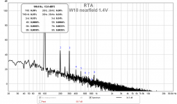
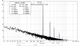
Here is a plot of H2 and H3 on the difference between the coils. I don't do this often so it well may be incorrect or just a plot of noise. The drive is 100 mV. More would be annoying at this hour.
Later I'll confirm what this is showing. . .
Attachments

At only 100mV this looks prone to sink into a sea of noise. You are effectively measuring the distortion that the current is subject to under voltage drive. Indirect measurement, but very close. At low levels there isn't much to see.
Once the driver's limits are reached this distortion will sky-rocket. And it should be extremely similar to the measured distortion of the current itself, identical to first order at least.
Once the driver's limits are reached this distortion will sky-rocket. And it should be extremely similar to the measured distortion of the current itself, identical to first order at least.
I do not know, we should have ask him. Maybe much higher power and cone displacement? Remember, he is in a speaker diagnosis business.
And I have shown a $205 driver. Cheap Chinese ones measure different.
On the other hand, W18's distortion also rises below 50Hz. But it is in percents then, not 60%.
And I have shown a $205 driver. Cheap Chinese ones measure different.
On the other hand, W18's distortion also rises below 50Hz. But it is in percents then, not 60%.
Last edited:
Assume an efficient PA midbass with lots of linear mechanical displacement but very little voice coil overhang. It's easy to overdrive it wrt electrically linear excursion capabilities. In such a case an adaptive pre-distortion of the signal could it extend the linear excursion (as would a true MFB). Only to a final frontier, that is, it's over when Bl has almost completely gone down and/or the driver brickwalls into the suspension limit.So then, what is Klippel doing to get 60% distortion from 30 to 60 hz?
So then, what is Klippel doing to get 60% distortion from 30 to 60 hz?
jn
The reason I asked, isn't that worse than a square wave?
Right 1/3, 1/5, .... series, so you have a driver driven to the point that the fundamental is actually suppressed and you can fix it to the few percent level at the same output SPL. I'm still missing something (and I might be it's not my field).
Looks like he is well below resonant frequency, so not much acoustical output of the fundamental. Big displacement and harmonics radiated.
Last edited:
- Status
- Not open for further replies.
- Home
- Member Areas
- The Lounge
- John Curl's Blowtorch preamplifier part III