So, it does look consistent with what I am thinking.
So, yah...😀 😕😉
jn
Or this way? This 2nd compensation makes the transfer function in fact equivalent to a current drive.
Attachments
In DVC driver there are 2 "L" as in the physical coils. In your schemas there is a third - I presume part of a electrical equivalent model? But why not 4?
Help! 🙂
//
Help! 🙂
//
Last edited:
No need for a measuring coil, for simulation. Subtractors make ideal coupling.
Better think about the gyrator. Voltage at its primary terminals is that famous back-EMF (I hate that term BTW). Should be included into compensation? This is my question.
Better think about the gyrator. Voltage at its primary terminals is that famous back-EMF (I hate that term BTW). Should be included into compensation? This is my question.
The intent is to NOT have any "back EMF" in the feedback. The subtraction of the coil voltages per my schematic guarantees zero by cancellation.
Your second does not do that.
jn
Your second does not do that.
jn
Are you suggesting a compensation like this?
On second thought, you are using the voltage across the .4 mh inductance as feedback.
My circuit cancels that out.. I assume the voltage across the gyrator is the real part of the terminal voltage?
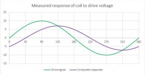
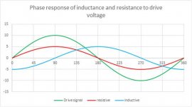
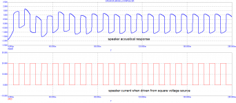
Here are the waveforms. The first is the composite voltage across the Ls and Rs. Ls is 90 degrees out of phase, Rs is in phase, so the composite or total, is somewhere in between.
The second is the individual components. The circuit intent is to subtract the out of phase content, as that is all reactance. Leaving just the resistive in phase component, which does all the work.
jn
Attachments
Last edited:
OK, thanks for the clarification, jn. However, please take into account what the voice coil in a real world is. The 1st scheme compensates just for Le value and non-linearity of Le. The 2nd scheme compensates for mechanical impedance as well and then you get in case is square voltage drive exactly square speaker current. Frequency response is then like that of the current drive.
Do not care about gyrator, imagine transformer and parallel instead serial connection.
Speaker output is at radiation impedance, out denomination in the schemes.
Speaker output is at radiation impedance, out denomination in the schemes.
I will wait what you get from real speakers. As now, Demian gets from the measuring coil same plots as I from simulation scheme No.2 (without control loops of course).
Last edited:
Connect it exactly as per the schematic. Connect the coils at the "top". Drive the primary coil, and look at the difference between coils.
The plot should show the losses.
Jn
I think this is what you asked for. Plus terminals connected, amp connected to one coil. looking at the difference between low side of undriven coil and amp return.
I won't be able to strap this to a feedback network for a while. The amp is a venerable HP467A.
The driver is this: Amazon.com: Goldwood Sound Dual Voice Coil 6.5" Replacement Speaker Woofer Black (GW-406D): Home Audio & Theater Goldwood sound GW 406D. Selected because the cheapest and quickest to get.
I have another amp I may be able tweak for this. Not sure yet.
Attachments
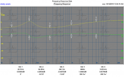
Nice, very well behaved data.
First pass was 25 dB range and 150 degrees phase shift.
Second using differential was 5 dB range and 45 degrees max phase shift..
First pass was 25 dB range and 150 degrees phase shift.
Second using differential was 5 dB range and 45 degrees max phase shift..
Last edited:
Not to take away from the ongoing speaker design, I might mention once again about the spirit of innovation that certainly was evident in the USA in the 1950's-70's, that seems sort of lost now, except for computers.
Apparently the 'need' for analog designs are much reduced these days, so people simply don't invest much funding, risk, or challenge into them. I am glad to have been a young man when solid state analog design was a huge challenge. I don't know what I could create today at that level. However, Jack Bybee seems to be one step beyond mere digital quality improvements at the moment.
Apparently the 'need' for analog designs are much reduced these days, so people simply don't invest much funding, risk, or challenge into them. I am glad to have been a young man when solid state analog design was a huge challenge. I don't know what I could create today at that level. However, Jack Bybee seems to be one step beyond mere digital quality improvements at the moment.
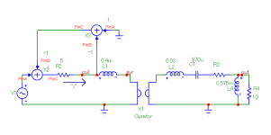
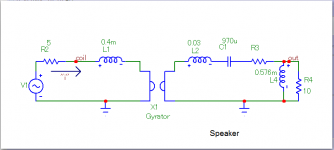
Thanks Pavel.In electric-mechanical lumped speaker circuit, the gyrator is used, as a standard, to allow electric-mechanical transformation, force = voltage, velocity = current, mass = inductance, compliance = capacitance, resistance = resistance. Serial = parallel. Bl is the gyrator constant.
Now in your electric-mechanical sim model
V1=Voltage source
R2=Voice coil DC resistance (Re)
L1=Voice coil self inductance (Le)
Gyrator=Bl (what value is your constant?)
L2=Total moving mass (Mm)
C1-suspension compliance (Cm)
R3=Total mechanical losses (Rm)
R4=Acoustic resistance (Ra) ?
L4= Air load mass (Ma) ?
George
Attachments
It just dawned on me. Duh.Thanks Pavel.
Now in your electric-mechanical sim model
V1=Voltage source
R2=Voice coil DC resistance (Re)
L1=Voice coil self inductance (Le)
Gyrator=Bl (what value is your constant?)
L2=Total moving mass (Mm)
C1-suspension compliance (Cm)
R3=Total mechanical losses (Rm)
R4=Acoustic resistance (Ra) ?
L4= Air load mass (Ma) ?
George
Everything that is coupled by flux is coupled through both coils. That means, eddy losses, acoustic transfer, Le, are all subtracted out.
The only thing that is not coupled is the resistance of the voice coil.
So the feedback parameter will be coil resistive voltage as well as any proximity effect resistance increase, which would be second harmonic.(edit: sorry, third)..
1audio, can you do a freq sweep using the coil diff setup looking for distortion?
Jn
Last edited:
Demian, could you pls. also measure the way I outlined in #11250?
The point is whether the JN-scheme actually results in a current-drive characteristic as it is expected from the theory, especially wrt damping and frequency response.
Of course, even more important is whether it renders less overall distortion than current drive because it's not at all clear which scheme is the winner. That would require acoustical measurement (after establishing identical SPL transfer curves, if required, which should be easy as they are expected to be close to identical anyway).
Is anybody else out there considering this setup for test? It would be great to have others try it, especially on a built ststem.
Jn
Jn
I'm really tempted but not in the near future due to possible re-location. I'm really interested in your tests of course.
//
//
Thanks Pavel.
Now in your electric-mechanical sim model
V1=Voltage source
R2=Voice coil DC resistance (Re)
L1=Voice coil self inductance (Le)
Gyrator=Bl (what value is your constant?)
L2=Total moving mass (Mm)
C1-suspension compliance (Cm)
R3=Total mechanical losses (Rm)
R4=Acoustic resistance (Ra) ?
L4= Air load mass (Ma) ?
George
Hi George,
Yes. Some remarks to R4//L4, they are a substitute scheme for mechanical radiating impedance transformed through membrane area (1/S^2) to mechanical side. R4 and L4 can be calculated from air density, membrane radius and area, and sound velocity. Bl = 0.2 in my simulation.
The point is whether the JN-scheme actually results in a current-drive characteristic.
I am not sure about JN scheme, but my simulation (No.2) resulted in a pure current drive from a pure voltage source. And there is an issue with transient response (resonance on acoustical side) as expected.
Attachments
- Status
- Not open for further replies.
- Home
- Member Areas
- The Lounge
- John Curl's Blowtorch preamplifier part III