Hi huggygood,
For a MOSFET source follower it is important to use a MOSFET with lhe lowest Crss possible, today they are a lot 🙂
As an example the FQPF2N60C ( https://www.mouser.fr/datasheet/2/308/FQPF2N60C-1306298.pdf ) has 4.3 pF and the STU9HN65M2 ( https://www.st.com/resource/en/datasheet/stu9hn65m2.pdf ) has 0.85 pF
There are others, like the FQPF8N60CFT (12 pF), the STF2N80K5 (0.5 pF ) ( https://www.st.com/resource/en/datasheet/stf2n80k5.pdf ), and the STF7N60M2 (0.68 pF
  ) ( https://www.st.com/resource/en/datasheet/stf7n60m2.pdf )
I have bought 10 pieces of each of them to make tests as they are not very expensive 🙂
Regards,
Marc
For a MOSFET source follower it is important to use a MOSFET with lhe lowest Crss possible, today they are a lot 🙂
As an example the FQPF2N60C ( https://www.mouser.fr/datasheet/2/308/FQPF2N60C-1306298.pdf ) has 4.3 pF and the STU9HN65M2 ( https://www.st.com/resource/en/datasheet/stu9hn65m2.pdf ) has 0.85 pF
There are others, like the FQPF8N60CFT (12 pF), the STF2N80K5 (0.5 pF
) ( https://www.st.com/resource/en/datasheet/stf2n80k5.pdf ), and the STF7N60M2 (0.68 pF ) ( https://www.st.com/resource/en/datasheet/stf7n60m2.pdf )I have bought 10 pieces of each of them to make tests as they are not very expensive 🙂
Regards,
Marc
Hi Vunce,
Yes you only need to put the jumper as indicated on the schema 🙂
As you are using DC I suggest to connect the GND to the input which is connected to pin 9 when using a 6N1P tube, but it is not critical...
Bye,
Marc
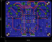
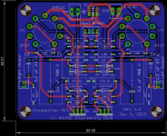
PS : I have squeezed the PCB in less than 10 cm, but to do that I removed the pot which was not very useful on board anyway 😀
Yes you only need to put the jumper as indicated on the schema 🙂
As you are using DC I suggest to connect the GND to the input which is connected to pin 9 when using a 6N1P tube, but it is not critical...
Bye,
Marc
PS : I have squeezed the PCB in less than 10 cm, but to do that I removed the pot which was not very useful on board anyway 😀
Hi Marc,
To bad you didn’t shrink the pcb before I ordered them 😀
This leads to another question, I’m using a chassis mounted volume pot that will connect to Direct Input on the pcb. The Bom spec’ed a 20K volume pot, will a 50K be ok for an alternate?
Cheers,
Vunce
To bad you didn’t shrink the pcb before I ordered them 😀
This leads to another question, I’m using a chassis mounted volume pot that will connect to Direct Input on the pcb. The Bom spec’ed a 20K volume pot, will a 50K be ok for an alternate?
Cheers,
Vunce
Hi Marc
I found them all at Farnell, it's cool!
I place my order early in the year and then I start my baby huey 6l6gc or 7591 according to my mood.
A very good evening 😉
I found them all at Farnell, it's cool!
I place my order early in the year and then I start my baby huey 6l6gc or 7591 according to my mood.
A very good evening 😉
Hi Marc,
I appreciate the shrinking of the pcb to save some peso's. I await the posting of the new gerbers. Thank you for all that you do.
Myles
I appreciate the shrinking of the pcb to save some peso's. I await the posting of the new gerbers. Thank you for all that you do.
Myles
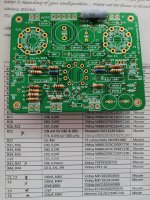
Hi Marc you might wanna fix the typo on silk screen for the MOSFET, newbies may have trouble obtaining the "FQFP2N60C". It's FQPF2N60C.
Hi EmeryBB,
Thanks for the warning 🙂
I copied the reference in the post 167 of Vunce who took it from the BOM where there was the error 😱
I have corrected everything and you will find it below...
Best regards,
Marc
Thanks for the warning 🙂
I copied the reference in the post 167 of Vunce who took it from the BOM where there was the error 😱
I have corrected everything and you will find it below...
Best regards,
Marc
Hi All. I need to put all high and low voltage recitifer and low voltage regulator with AC power source into individual case. Due to my amp case not large enough and want less pay $ for my another tube amp (it can reuse this DC supply). I am not sure this arrangement, all DC given from seperated box will have any problem and concern that i need pay more attention in advance ?
Hi ckwong99,
For the EL34 Baby Huey, you can use DC or AC voltage for the high voltage (max 275 VAC or 385 VDC if using 400 V capacitors) and for the 6.3 V heater, BUT YOU MUST USE ONLY AC for the 50 V bias & driver supply because the positive AND the negative voltage are rectified on board from the AC input
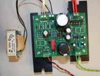
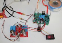
The power supply for the preamplifier is serial type and fixed by 3 x 100V Zener, of course it is possible to use different Zener values 🙂
I have also made a variable one with a regulator, see picture...
Rgds,
Marc
For the EL34 Baby Huey, you can use DC or AC voltage for the high voltage (max 275 VAC or 385 VDC if using 400 V capacitors) and for the 6.3 V heater, BUT YOU MUST USE ONLY AC for the 50 V bias & driver supply because the positive AND the negative voltage are rectified on board from the AC input
The power supply for the preamplifier is serial type and fixed by 3 x 100V Zener, of course it is possible to use different Zener values 🙂
I have also made a variable one with a regulator, see picture...
Rgds,
Marc
Attachments
Thx . i know that but i only want to know if external suply give dc to amp (except 50vac) . whether it will have problem on a long transmission dc power line for high voltage and filament low voltage ?
R39 is dependent of the bias voltage and of the output tubes, with 50 VAC as recommended it can be between 10 k to 18 k without problem. In older BOM it was specified at 39 k which is definitely too high 😡
Rgds,
Marc
Rgds,
Marc
Updated BOM for EL34 & EL84 Baby Huey
Hi Happy Baby Huey Builders,
To make your DIY work easier, I have made a new updated BOM for both EL34 and EL84 Baby Huey PCB 😀
I do not plan to make a separate thread for the EL84 Baby Huey because both versions are very similar and I think it is better to have all the information in only one thread.
For those who are interested by the history of the EL84 Baby Huey, they can read here EL84 Amp - Baby Huey the long thread started by Ian (gingertube) in 2006 !!! This is where all started for me in October 2016 (post 1670), 10 years after the first post, and at that time I would not have believed that more than 500 PCB that I have designed will be built, I didn't even know how to make a Group Buy and hopefully after the two first GB of 200 boards, Prasi accepted to continu the job and has produced 300 boards more
Now the Baby Huey story is finished for me and I hope to have the time in 2019 to make my long delayed Quad KT120 with Cathode feedback and autobias 😎
Merry Christmas and Happy New year,
Marc
Attachments
- Home
- Amplifiers
- Tubes / Valves
- EL34 Baby Huey Amplifier