Thanks for the reply Pink, I understand that your boards do not use fets ( same as Delta), but are they the Mk1 or Mk2 KSA50? Seems to be a difference of opinion regarding versions when searching on the internet.
Best Regards
Alan
Hi Alan,
I've allready answered that question to you few years ago. The mk1 after '83 and the first version of mk2 had the same circuit. The only difference is in the cooling fan placement (mk1 on the top, mk2 on the bottom). The mk2 version had relay speaker protection, mk1 had fuses. The final mk2 version had the mosfet ccs, same as ksa100mk2.
The first edition of mk1 had different circuit and lower rail voltage (cca 36V)/high (full) bias. The Mk1 after 83 and mk2 versions had higher rails (cca 50V)/lower bias. So, you can call Delta/Pinkmouse boards either mk1 after 83, or mk2 first edition.
Last edited:
Still in planning stages and waiting for a few resistors on back order.
I have got a few questions.
should I use kemet ALS70 51,000uf 63v capacitors x 4 2 for each mono block £19 each are these suitable (RS components).
Just that i read somewhere 105c are better but ALS80 are twice the price.
also are SMC silver mica 39pf 500v £2 each a good choice for the 39pf on this pcb.
Are mills 0.5R 5w resistors a good choice for the output transistor pcbs 0R5 position also noticed some people are using 0.68R (hifi collective).
what is a good choice of 0.1uf capacitors for this pcb I was thinking of Audyn true copper max 0.1uf £13.99 (going by humble homemade capacitor test) but they are large 21mm x 45mm so i would have to mount them onto back of pcb.
500Va 32v x 2 transformers from airlink transformers £50 each should give me 48v DC I hope.
I am going to use two pc fans in push pull at a lower speed to keep heatsink cool and noise down will I be able to run in full class A at 48v.
Is it ok to mount pcb above transformer Like I have it in photo.
Should I add speaker protection or is it not needed.
Just do not want to start ordering these parts if they are wrong in any way.
Attachments
![20181127_120619[2042].jpg](/community/data/attachments/654/654485-796deb85b48a7e1c9ddc99e3425f708d.jpg?hash=eW3rhbSKfh)
![20181127_120636[2043].jpg](/community/data/attachments/654/654507-c349ecf67f8cb249929deea5f8409267.jpg?hash=w0ns9n-Msk)
Last edited:
Pink, thanks for your reply, I sincerely hope the house move goes well, I know it can be a trying time. I've built Symasym a couple of years ago and agree a very nice amplifier. Just that I fancy another A .
Best Regards
Alan
Best Regards
Alan
Neychi, thanks for the reply. Please forgive an elderly chap whose memory isn't what it was, I had forgotten I asked this question several years ago. Your answer is very precise, now I understand that the last version of the Mk 2 had the fet CCS. Now the question is, does the fet CCS version sound better than the version without it?
Best Regards
Alan
Best Regards
Alan
Still in planning stages and waiting for a few resistors on back order.
I have got a few questions.
500Va 32v x 2 transformers from airlink transformers £50 each should give me 48v DC I hope.
I am going to use two pc fans in push pull at a lower speed to keep heatsink cool and noise down will I be able to run in full class A at 48v.
Hi
32V transformer in Class A bias will give you about 39VDC under load at Class A. If you wish you get 48VDC at heavy class A bias you need 40V transformers.
When we talk about Class A bias you multiply the AC by 1.2, not 1.41...
Just wanted to warn you if you do any calculation should know you will have under 40V under load.🙂
Greetings
Thank you I will get 40v transformers instead I have always timed by 3 then halved to get ac to dc voltage in the past.
Still in planning stages and waiting for a few resistors on back order.
I have got a few questions.
should I use kemet ALS70 51,000uf 63v capacitors x 4 2 for each mono block £19 each are these suitable (RS components).
Just that i read somewhere 105c are better but AL S80are twice the price.
also are SMC silver mica 39pf 500v £2 each a good choice for the 39pf on this pcb.
Are mills 0.5R 5w resistors a good choice for the output transistor pcbs 0R5 position also noticed some people are using 0.68R (hifi collective).
what is a good choice of 0.1uf capacitors for this pcb I was thinking of Audyn true copper max 0.1uf £13.99 (going by humble homemade capacitor test) but they are large 21mm x 45mm so i would have to mount them onto back of pcb.
500Va 32v x 2 transformers from airlink transformers £50 each should give me 48v DC I hope.
I am going to use two pc fans in push pull at a lower speed to keep heatsink cool and noise down will I be able to run in full class A at 48v.
Is it ok to mount pcb above transformer Like I have it in photo.
Should I add speaker protection or is it not needed.
Just do not want to start ordering these parts if they are wrong in any way.
Hi Dave,
I've looked at the data sheet for ALS70 51,000uf 63V and the ALS80 47,000uF and they both have the same ESR (100Hz) and impedance (10KHz).
If I was buying these I would go for the ALS70 and save the money for something else.
Go with the mica - for caps that are pF.
I would not go higher than 0.5R. The Mills are non inductive and don't use steel endcaps, so they are not attracted to magnets.
If you are bi passing filter caps, you can use Wima 0.1uF 100V polypropylene etc.
The caps that you are referring to (Humble Homemade capacitor test) are used in the signal path or in speaker cross overs.
I would not mount the PCB over the transformer as you are most likely to pickup hum and/ or noise.
A "better" arrangement would be to have the heatsink between the transformer and the PCB. It might act as a shield.
Hope that helps.
Last edited:
where to look?
There's TO3 mounting brackets and TO3 mounting brackets
Attachments
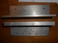
There's TO3 mounting brackets...
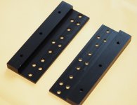
Nice 😀
Found these on flebay, not quite what I wanted, but they will do.
Attachments
Neychi, thanks for the reply. Please forgive an elderly chap whose memory isn't what it was, I had forgotten I asked this question several years ago. Your answer is very precise, now I understand that the last version of the Mk 2 had the fet CCS. Now the question is, does the fet CCS version sound better than the version without it?
Best Regards
Alan
Well, some people says that the latest version sounds best, some people prefers first mk2. I had no opportunity to listen every version of original ksa50 (just first mk2) but I can tell you that higher rail voltage do things better. I've finished two clones, one with Delta boards, and 37V DC rails (1.8 A bias, 3 pair of output devices, 300mV per device), and one with mosfet-ccs, 48 V DC rails (1,3 A bias, 2 pair of output devices, 325mV per device). The difference between this two amps is so obvious. The later has more punch, more authority but still has smooth silky highs which is exactly what I remember from listening original KSA50.
Dean
Hi Dave,
I've looked at the data sheet for ALS70 51,000uf 63V and the ALS80 47,000uF and they both have the same ESR (100Hz) and impedance (10KHz).
If I was buying these I would go for the ALS70 and save the money for something else.
Go with the mica - for caps that are pF.
I would not go higher than 0.5R. The Mills are non
inductive and don't use steel endcaps, so they are not attracted to magnets.
If you are bi passing filter caps, you can use Wima 0.1uF 100V polypropylene etc.
The caps that you are referring to (Humble Homemade capacitor test) are used in the signal path or in speaker cross overs.
I would not mount the PCB over the transformer as you are most likely to pickup hum and/ or noise.
A "better" arrangement would be to have the heatsink between the transformer and the PCB. It might act as a shield.
Hope that helps.
Thankyou this has been really helpful I will change my layout and use wims caps.
I am still wondering what size transformers the original krell mk2 used.
I read the really early mk1 version used 25v - say my pcb and transistor boads say -48v +48v.
Thankyou this has been really helpful I will change my layout and use wims caps.
I am still wondering what size transformers the original krell mk2 used.
I read the really early mk1 version used 25v - say my pcb and transistor boads say -48v +48v.
Perhaps Dean can help you with output voltage and VA for the transformers. I trust someone who has built both and compared.
What boards have you got?
2 x 400VA
For 48V DC loaded, you will need 36-0-36 secondaries.
Thank you for your reply Neychi so my guess is the original krell ksa 50 mk1 used 25v-0-25v transformers and the krell ksa 50 mk2 36v-0-36v transformers.
Thank you for your reply Neychi so my guess is the original krell ksa 50 mk1 used 25v-0-25v transformers and the krell ksa 50 mk2 36v-0-36v transformers.
More likely 28-0-28V AC. You have to keep in mind that this transformer has a good voltage regulation, otherwise the voltage drop under the load will be higher.
There were many variations in the supply voltage in those early Krells, ranging from 47V DC to 51V DC (after '83 models), depending on year of production and the country where the device was sold / used and the supply voltage of the distribution network.
Last edited:
More like 28-0-28V AC. You have to keep in mind that this transformer has a good voltage regulation, otherwise the voltage drop under the load will be higher.
There were many variations in the supply voltage in those early Krells, ranging from 47V DC to 51V DC (after '83 models), depending on the country where the device was sold / used and the supply voltage of the distribution network.
I have noticed most transformers are 230v AC input even the ones made in the Uk by airlink transformers.
My mains voltage is 240v AC so i normally get about 5% higher output voltage
at transformers so a 36V-0-36v gives me 37.8v-0-37.8v as a example.
gaborbela stated that I need to multiply Ac by 1.2 not 1.41 to get dc voltage in class A.
Thanks again neychi.
Hi neychi, could I ask another question regarding the KSA with 48V rails, two output devices per channel and 325mV across emitter resistors giving 1.3A bias. I assumed emitter resistors to be 0.5 Ohm. This equates to 27W class A RMS into 8 Ohm, then it transitions into AB. Is this correct, or have I misunderstood?
Best Regards
Alan
Best Regards
Alan
- Home
- Amplifiers
- Solid State
- Krell KSA 50 PCB