Anyone tried this amp board?
TDA8954TH Class D High Power Dual-Channel Digital Audio Amplifier Board 420 I1A2 192948093630 | eBay
I think to purchase one and to try to convert it to 4 SE channels to make active speakers with a DSP.
And maybe one cheaper mono board with the same TDA8954 IC for subwoofer.
How it sounds for full range speakers?
The default sampling frequency is 350kHz, but it can be set up to 500kHz, according the datasheet.
I didn't try exactly the same board but 8 years ago I used 8954 in commercial design and have to say that idea to use sendust-125 core in the output filter is very bad. 8954 using feedback before filter, hence you need some coils with good linearity, as IR used micrometals#2 or gapped ferrite.
I used Search too, before opening the thread.
This is different board, with different parts and different routing...
IVX, I don't know what are the cores of the output filters of these boards.
Thanks for the information!
I used Search too, before opening the thread.
This is different board, with different parts and different routing...
IVX, I don't know what are the cores of the output filters of these boards.
Thanks for the information!
sorry I do not want to blame you. it is always a try to read other threads.
air coils look like so:
http://www.ultrafinecopperwire.com/...-coil-wire-bobbin-toroid-filter-inductor.html
the ouput coils are mounted near the terminals of the speakers.
For SE = 2 Speakers in series you use 2x 4ohm speakers per channel?
This board is with two TDA8954 chips, both in BTL configuration.
I think to convert it to 4 single ended channels.
The speakers are with 8 ohm impedance.
I think to convert it to 4 single ended channels.
The speakers are with 8 ohm impedance.
I see black rings with marking -125 at their pics, it is 99% of probability if sendust cores. If it so, I guaranty THD >.5% ))
Hi, I bought this exact same board. Just finished recapping with Panasonic FS caps because it arrived with one dented cap so I just replaced everything with much better ones. I'm sorry to not be able to offer any impressions about sound quality though because I have no way to test it right now as I don't have the necessary wires, etc.
This person on youtube thoroughly tested this unit:
YouTube
This amp puts out about ~220 watts per channel @ 1% THD.
An externally hosted image should be here but it was not working when we last tested it.
An externally hosted image should be here but it was not working when we last tested it.
An externally hosted image should be here but it was not working when we last tested it.
This person on youtube thoroughly tested this unit:
YouTube
This amp puts out about ~220 watts per channel @ 1% THD.
Last edited:
just for the first try:
do not use the Class D amp without load
do not use your good speakers - dummy load = resistor
use some cheap chassis from old spakers or 2nd hand....
often the chinese board use fake caps...its marked normaly with better values --> voltage / capacity
do not use the Class D amp without load
do not use your good speakers - dummy load = resistor
use some cheap chassis from old spakers or 2nd hand....
often the chinese board use fake caps...its marked normaly with better values --> voltage / capacity
just for the first try:
do not use the Class D amp without load
do not use your good speakers - dummy load = resistor
use some cheap chassis from old spakers or 2nd hand....
often the chinese board use fake caps...its marked normaly with better values --> voltage / capacity
Do you think replacing them with the same specs as the label on the capacitors could be a problem? I have no idea how fake their labels can be 🙂
Do you think replacing them with the same specs as the label on the capacitors could be a problem? I have no idea how fake their labels can be 🙂
no there is no problem. i am very sensitive in the voltage of the fake caps because if you power up with the "labeled" voltage it might be that the fake caps explore !!!😱
with your caps there is no risk- just keep 2-3Volt under the max of the cap if you power up
chris
tacoman5000, as I see he only measured the output voltage, it is not power measurement, which uses a resistor load as a standard. BTW, that IC has a quite low efficiency and without serious heatsink or fan you'll never get >150W per channel for a minute, rather 100W. The main problem for that particular board is cheap sendust inductors as I guess. Try to read black core marking please, to be sure if I'm right/wrong.
no there is no problem. i am very sensitive in the voltage of the fake caps because if you power up with the "labeled" voltage it might be that the fake caps explore !!!😱
with your caps there is no risk- just keep 2-3Volt under the max of the cap if you power up
chris
Ah, alright thanks.
tacoman5000, as I see he only measured the output voltage, it is not power measurement, which uses a resistor load as a standard. BTW, that IC has a quite low efficiency and without serious heatsink or fan you'll never get >150W per channel for a minute, rather 100W. The main problem for that particular board is cheap sendust inductors as I guess. Try to read black core marking please, to be sure if I'm right/wrong.
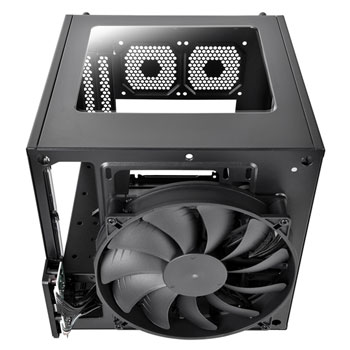
I plan to mount this entire amplifier rig (with a bunch of other things) in a mini-ITX computer case with a large fan:
An externally hosted image should be here but it was not working when we last tested it.
Sorry, I don't see any clear markings in the core. Any ideas on what else I can do to improve this amp?
Waiting for your response for the sound quality.
I saw that video, before opening the thread. There is some ringing in the square wave. Maybe some R-C snubbers can be added, to reduce the ringing.
For me the capacitance after the bridge rectifiers is too small - for me it's better to remove the two bridge rectifiers and supply the board directly with +/- DC voltages with at least 10000uF per rail.
In my opinion, the sound quality of that IC is close to junk. At least without extra feedback loop with integrator, regarding formal specs as THD and S/N, it is low end for sure. I have posted the schematic(thread = TDA89** fasten belt) of my feedback-mod which I used for numerous caraudio brands years ago.
Waiting for your response for the sound quality.
I saw that video, before opening the thread. There is some ringing in the square wave. Maybe some R-C snubbers can be added, to reduce the ringing.
For me the capacitance after the bridge rectifiers is too small - for me it's better to remove the two bridge rectifiers and supply the board directly with +/- DC voltages with at least 10000uF per rail.
Will update when I have tested these with speakers. I'm trying to look for dirt cheap speakers to test this amp with.
In my opinion, the sound quality of that IC is close to junk. At least without extra feedback loop with integrator, regarding formal specs as THD and S/N, it is low end for sure. I have posted the schematic(thread = TDA89** fasten belt) of my feedback-mod which I used for numerous caraudio brands years ago.
I probably won't even be able to use this amp anywhere near its full capabilities so I have no doubt I'd be getting clean power from it. Also, the anecdotal reports from other users about the sound have all been positive. I think that's good enough for me for the amount I spent on it 🙂
- Home
- Amplifiers
- Class D
- TDA8954TH - XH-M252 board - anyone?