Rodeodave
Hard to tell about my 431s - On those I can read it says 431c
Have ordered A version and in the process of changing caps
Thanks
Bob
Hard to tell about my 431s - On those I can read it says 431c
Have ordered A version and in the process of changing caps
Thanks
Bob
Thanks Botte. Your response helps to clear up things. Mine is a new build so I will go with C1,C2 at 220uf and C3,C4 at 47uf, all the rest 220uf.
I realize that we all have different brand preferences for caps. What brand here seems to have worked best for you? Also what voltage should these be? Bypass or not since the board has provision for it?
Nash
I use the Elna SILMIC II Series 50V for the bootstrap 35 for the rest. I do bypass them with the vishay MKP 1837.
I use the Elna SILMIC II Series 50V for the bootstrap 35 for the rest. I do bypass them with the vishay MKP 1837.
What value 1837?
Thanks again.
nash
Tractor is gone
Thank for all your help guys 😀😀😀😀😀
Changed C1,C2 to 220uF and C3,C4 to 50uF (2 100uF in series) as suggested and didn't hear a putt putt.
Will re-bias later today.
Again many thanks !!!!!!
Best
Bob
Thank for all your help guys 😀😀😀😀😀
Changed C1,C2 to 220uF and C3,C4 to 50uF (2 100uF in series) as suggested and didn't hear a putt putt.
Will re-bias later today.
Again many thanks !!!!!!
Best
Bob
What value 1837?
Thanks again.
nash
.01uF
https://www.mouser.com/ProductDetai...GAEpiMZZMv1cc3ydrPrF%2b30hQTSgFppuyBVyjPLnYo=
See http://www.humblehomemadehifi.com/Cap.html
Any reason you have omitted C7,C8?
Thanks.
Nash
Nelson showed a plot with and without the bootstrapped output mod and the only difference I could see was that the output power increased.
Nelson also showed a distortion plot of different Vds voltages and the one operating at 25 volts had the lowest distortion figure.
I will probably try both versions.
BDP
Thanks, will incorporate. nash
Nelson showed a plot with and without the bootstrapped output mod and the only difference I could see was that the output power increased.
Nelson also showed a distortion plot of different Vds voltages and the one operating at 25 volts had the lowest distortion figure.
I will probably try both versions.
BDP
Thank you for explaining. nash
Been listening on the main system of a few weeks now. This to me is much better than the Version one. It has much detail without being bright sounding and the bass is better defined.
I will swap in my f3's, which have been my favorite amps and see how they compare.
I built both the M2 and Sony Ver 1 which both have the input transformers and they were just not to my liking, not bad by any means, just didn't capture my attention when I go through my music collection. Just my two cents worth?
Attachments
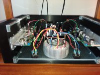
first one is up and running...
Two questions:
1. I have T18 measured -0.2v, while almost zero at output. Is it OK?
2. Both R5 and R6 have VD across them of 1.12V against 1.2V - 1.5V in the manual, seems underbiased a bit. Can not get more with P3/P4. Is it OK?


Two questions:
1. I have T18 measured -0.2v, while almost zero at output. Is it OK?
2. Both R5 and R6 have VD across them of 1.12V against 1.2V - 1.5V in the manual, seems underbiased a bit. Can not get more with P3/P4. Is it OK?

well, another board is a bit worse - R5/R6 vd is 0.6V maximum, so it's about 1V at T18, while final stage seems OK. Should I make a manual selection of J313/K2013 for higher Vgs?
0.6V across R5 and R6 seems quite low. I guess it may be a combination of low Idss
jfets/high Vgs mosfets. I don't think you should select higher Vgs mosfets. (If
anything, that will likely make things worse.)
I think you need to increase the total resistance of R35+P3 and R34+P4.
1V offset at T18 is higher than Papa's recommendation of 200mV.
Also, are you really running the channels with just the brackets without
bolting them to heatsinks?
Hopefully others can chime in.
0.6V across R5 and R6 seems quite low. I guess it may be a combination of low Idss
jfets/high Vgs mosfets. I don't think you should select higher Vgs mosfets. (If
anything, that will likely make things worse.)
I think you need to increase the total resistance of R35+P3 and R34+P4.
1V offset at T18 is higher than Papa's recommendation of 200mV.
Also, are you really running the channels with just the brackets without
bolting them to heatsinks?
Hopefully others can chime in.
I will be trying to increase 500ohm to 750. On both channels. As for the heatinks, I am not going over 50mV on R32 for now. Once fully installed in chassis, I will increase vfets bias.
Ok, now two boards are up and running. R34 and R35 replaced with 333ohm, got 1V voltage drop at R5 and R6, 0.1V at T18 and about zero output. Now have to put them into the chassis and - to listen. Thank ya all for your support!!!


Late to the build but any way to purchase a kit now? or are these long gone?
Boards are still available in diyaudio store. Other parts are available elsewhere, except v-fets. In order to proceed you need two matched pairs of SK82/SJ28 or at least SK60/SJ18.
Well, the VFets don't need to be matched, but you need to know their Vgs at 0.5A Ids in order to safely bias the circuit. If you manage to somehow find the VFets, the Vgs grading can be done according to the attached schematic (courtesy of Nelson Pass).
Attachments
- Home
- Amplifiers
- Pass Labs
- Sony vFET Amplifier Part 2