R1 must have about 0.6V from leg to leg, which is Q1's Vbe if working. M1 must have 4-5V from g pin to s pin if working. M2 3-4 V between those pins if working.
Hi Salas,
I guess 3300µF is not enough for C1, Rf/C1 and local decoupling ripple wise? Not much CC, 3 opamps only to supply... I got these caps and if they are enough it's... enough.
Again, thanks for your endless help.
I guess 3300µF is not enough for C1, Rf/C1 and local decoupling ripple wise? Not much CC, 3 opamps only to supply... I got these caps and if they are enough it's... enough.
Again, thanks for your endless help.
Maybe Q1 is faulty, I have same 12,8v. on R1 from leg to leg.
Then M1 has
12v. on G pin
12,8v. on S pin
0v. on D pin
M2 has no voltage at all.
Then M1 has
12v. on G pin
12,8v. on S pin
0v. on D pin
M2 has no voltage at all.
Change Q1 for start. Any PNP with same pin order will work in the board if you are not having the exact low noise type spare for now.
Hi Salas,
I guess 3300µF is not enough for C1, Rf/C1 and local decoupling ripple wise? Not much CC, 3 opamps only to supply... I got these caps and if they are enough it's... enough.
Again, thanks for your endless help.
Its enough for your loading needs and for filtering
P.S. When you will replace Q1 also check mV drop from leg to leg on R4. If its running something normal like 2mA that will make 540mV. There is range in mV reading due to J1's various IDSS but not order of magnitude range. So to know J1 is not the fault's root problem for draining high current through that kills Q1.
Hi Salas,
I am assembling parts for a pair of UltraBibs, and I hope that you can give me your view on whether FQP13N10/12P10 would be acceptable alternatives for IRF530/9530 at the M2 position?
They appear to have similar performance characteristics, e.g. Rds-on pretty close, the FQP's have a little lower available continuous drain current and perhaps are not quite as thermally robust, FQP's appear to have lower dynamic capacitance.
Which characteristics are important at M2?
Thanks,
Keith
In simulation (with ON Semi published Spice model) the FQP13N10 looks precarious to oscillate as the system loses 20deg phase margin vs using the IRF530. It may prove otherwise in practice if you have the time to test it. Having lower dynamic capacitance is nice but that's straightforward only for M1. M2 has to fit best the rest of this circuit's parameters. The IRF630 looks good for M2 as well.
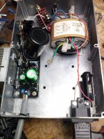
Q1 replaced. Now somewhat better, lights up but when loaded leds blink and can't load the DAC (I tested the draw is pretty low, using basic mobile charger I measured 370mA/5.2v.)
I also checked mV drop from leg to leg on R4: 357mV.
I also checked mV drop from leg to leg on R4: 357mV.
R1 has 9,2v.- 8,6v.= 0.6V from leg to leg
M1 readings:
3v. on G pin
8,6v. on S pin
5v. on D pin
On M2 :
3,5v. on G pin
0v. on S pin
5,1v. on D pin
M1 readings:
3v. on G pin
8,6v. on S pin
5v. on D pin
On M2 :
3,5v. on G pin
0v. on S pin
5,1v. on D pin
The Mosfets seem alright. Try normal R1 no 2W trimmer there, maybe it makes the M1 section unstable
Salas, thanks very much, I appreciate your patience. In my naivete' I imagined this might be answerable my inspection.
Thanks again,
Keith
Yikes. This sounds less than optimum. I will need to learn how to use SPICE.In simulation (with ON Semi published Spice model) the FQP13N10 looks precarious to oscillate as the system loses 20deg phase margin vs using the IRF530.
I don't think I know how to test this, but I will do a search for "how to test phase margin" should I try the 13N10 in this circuit.It may prove otherwise in practice if you have the time to test it.
It seems prudent to stick with the published values, but I'll have a peek at the IRF630 too.M2 has to fit best the rest of this circuit's parameters. The IRF630 looks good for M2 as well.
Thanks again,
Keith
- Home
- Amplifiers
- Power Supplies
- Salas SSLV1.3 UltraBiB shunt regulator