Thank you Howie, not much documentation has been left. I found one photo of the inside.
Power supply was in a separate Al box, in fact 2 power supplies one for each channel. Input BNC's were connected directly to the metal case to minimize RFI input.
Nice layout, I am a sucker for symmetry, but if the right and left channel PCBs are not mirror images, won't that invert one channel? (JK)
Sweet!
Howie
, but if the right and left channel PCBs are not mirror images, won't that invert one channel? (JK)
Howie
Definitely! 😀
I will learn and make it better next time 😉
Here is a link to the WBT Product: nextgen™ RCA Connector - WBT-0110 Cu
I don't see how they overcame the fundamental dimensional constraint. I'm not about to buy some to put on the network analyzer to verify their claims. Not even sure what to use for the for the mating connector and nothing in the cal kits would be helpful.
I don't see how they overcame the fundamental dimensional constraint. I'm not about to buy some to put on the network analyzer to verify their claims. Not even sure what to use for the for the mating connector and nothing in the cal kits would be helpful.
Here is a link to the WBT Product: nextgen™ RCA Connector - WBT-0110 Cu
I don't see how they overcame the fundamental dimensional constraint. I'm not about to buy some to put on the network analyzer to verify their claims. Not even sure what to use for the for the mating connector and nothing in the cal kits would be helpful.
You have to use it with WBT nextgen rca jack to get a 75 ohm connection...
I would kill to have some calibration kits! All I have is APC-7, would love an "N", "BNC" and "SMA". Looking at the prices, I simply can't afford one, never mind three! Open, short and 50R sets.
Hi Pavel,
That is some lovely work! Nice and clean, and I doubt you have a problem with RF ingress. Sharp looking stuff. As for the RCA connectors, they aren't locking. Just a friction fit. I can see why you went to BNC connectors.
-Chris
Hi Pavel,
That is some lovely work! Nice and clean, and I doubt you have a problem with RF ingress. Sharp looking stuff. As for the RCA connectors, they aren't locking. Just a friction fit. I can see why you went to BNC connectors.
-Chris
It costs way too much. Simply reducing the shell continuity from a full 360 degree circumfrentially to almost a double stripline is a simple thing to do.I won´t dispute that this might be even more ingenious, but do still think that the WBT (or J.Reich´s) idea was ingenious.
Not sure. But the issue is that normal people see the geometry and say...the capacitance has to go below free space in order to get the impedance up...completely disregarding the inductance..nextgen modified the inductance, but their solution requires a modified female.I remember that you couldn´t disclose your idea a lot of years back, but maybe the constraints are relieved by now so that you could share it?
The patent lawyers here are really funky when it comes to spending their time getting a patent, they want to make sure there is a good return.
A cheap and fancy solution to a problem that nobody cares about can't be considered a reasonable return. A few hundred or even ten thousand units per year, where the solution costs pennies ain't exactly "return". Sigh..
The theory is sound. Think of a wire pair from a cat5e cable. 100 ohms twisted. spread them the radial distance of an rca, impedance goes up. Put a second conductor opposite the core, impedance drops. A specific number of outer wires spaced equally circumferentially and you eventually get down to 50 ohms. Nextgen did it with wider shield helix (IIRC).I don't see how they overcame the fundamental dimensional constraint. I'm not about to buy some to put on the network analyzer to verify their claims. Not even sure what to use for the for the mating connector and nothing in the cal kits would be helpful.
You have to use it with WBT nextgen rca jack to get a 75 ohm connection...
Nextgen does indeed require their female/male combo to work.
Jn
Hi DF96,
-Chris
I'm confused by this. Are you agreeing with me?No RCA is 75R or 50R. The ratio between inner and outer simply will not allow this; as I said, I would guess something more like 30R. The best you can do is add series inductance to offset the shunt capacitance so that in lower frequency circuits the combination does not look too far from whatever impedance you want. This will be plenty good enough for uncritical uses such as digital audio.
I am not aware of any instrumentation use for any sort of RCA.
-Chris
What do you need to measure and with what combo? I have also TEK TDR system. Besides network analyzers to cover audio to microwaves.
Usually, with HP gear and others, you dont need to do a precision Cal with standards for general purpose measurments. Their accuracy is so good without.... you wont miss the <..01dB difference. However you do need to factor out the test setup/layout wiring strays. Do a loop thru and save and subtract from DUT test. Most analyzers will do this for you from thier front panel op.
But it isnt enough to measure the cable with connectors (male and female) only.... you have to have it driven and loaded with real Z of the gear to be used to see the over-all final affect. And connections to connector of the cable with pig-tail leads (shield, for example) is not OK. The braid or shield needs to be connected to the body 360 degrees to maintain Z thru the cable/connector combo.
THx-RNMarsh
Last edited:
Definitely! 😀
I will learn and make it better next time 😉
Your designs should be in production, I was really impressed by the preamp cards I got from you! I do note your unbalanced output have the shell isolated from the chassis...
Cheers,
Howie
Thank you Howie, this would be a full-time job then and audio has always rather been my hobby than a job to make a living. It is really difficult to start real and successful production.
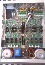
Thank you Howie, not much documentation has been left. I found one photo of the inside.
Power supply was in a separate Al box, in fact 2 power supplies one for each channel. Input BNC's were connected directly to the metal case to minimize RFI input.
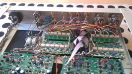
This is my GainWire mk3 CFA, balanced dual mono. Not so nice wiring comparing to yours Pavel.
Damir
Attachments
This is my GainWire mk3 CFA, balanced dual mono. Not so nice wiring comparing to yours Pavel.
Damir
Wow, that's a lot of good work, Damir! I have to admit that I do not prefer unshielded signal wires inside the box, for the reason of measurable pick-up of RFI/HF induced voltages.
Wow, that's a lot of good work, Damir! I have to admit that I do not prefer unshielded signal wires inside the box, for the reason of measurable pick-up of RFI/HF induced voltages.
Thank you Pavel, I could change some wiring for shielded in the future, for now I don't have problem with RFI/HF pickup. Input impedance is fixed 10k and output impedance is very low.
for now I don't have problem with RFI/HF pickup.
Damir, give it a try with a fast scope (>100MHz) at high sensitivity, like 2mV/div, or a HF spectrum analyzer. IME it is impossible not to see the difference when changing from unshielded wires to well shielded coax. cables, like RG-179. Not only outside-box fields are a source of HF pollution, but also power supplies inside the box, or digital circuits of any kind, if used. I have not understood, by now, why audio designers use unshielded, bare wires.
Damir, give it a try with a fast scope (>100MHz) at high sensitivity, like 2mV/div, or a HF spectrum analyzer. IME it is impossible not to see the difference when changing from unshielded wires to well shielded coax. cables, like RG-179. Not only outside-box fields are a source of HF pollution, but also power supplies inside the box, or digital circuits of any kind, if used. I have not understood, by now, why audio designers use unshielded, bare wires.
Thanks again Pavel. What shielded cable do you suggest for balanced connection?
It seems the good RCA is exclusively designed for critical high end digital audio application. Less critical and mundane application such as instrumentation and pro audio has to make do with cheaper connector like BNC. 😀... I am not aware of any instrumentation use for any sort of RCA.
![sub_wall_body1.1_1000[1].jpg](https://www.diyaudio.com/community/data/attachments/641/641987-49e002d6a2e5cd327cf42e23f9f0509f.jpg?hash=SeAC1qLlzT "sub_wall_body1.1_1000[1].jpg")
As I said, you can add series inductance but then you don't have a 75R connector, just a 30R-ish connector with a matching network which limits the bandwidth. This may be good enough for some applications - especially those which don't really need 75R connectors at all such as SPDIF.Jakob2 said:The WBT nextgen plug and socket _are_ 75 Ohm as they found an ingenious solution.
You could add ferromagnetic material to boost the inherent inductance. That could get you a connector which is really 75R at the cost of limiting power handling and possibly adding signal distortion, but then you still have the problem that a transition from 75R of one size to 75R of a different size still gives some reflections.
Are you saying what what they have made is not a 75R RCA, but a connector which when used as a pair provides 75R but will also mate with normal RCA (and then not give 75R)? That eases the problem; it is always easier to solve a problem when you have the freedom to change the problem.Jakob2 said:You have to use it with WBT nextgen rca jack to get a 75 ohm connection...
No. I was disputing your claim that RCA is 75R, or that some RCA is 75R. As far as I can see, you can have one of the following:anatech said:I'm confused by this. Are you agreeing with me?
1. genuine RCA, not 75R
2. RCA, with impedance matching network such as series inductance - limits bandwidth
3. RCA, with extra ferromagnetic - 75R but limits signal handling and probably bandwidth
4. not RCA, but 75R, yet will mate with RCA
Some people may wish to call 2, 3 or 4 '75R RCA', especially when they hope to take money off you.
Hi Pavel,
-Chris
Just curious. I tend to use RG-174 for internal and short runs. Unless you have easy access to RG-179, is there another reason why you would choose this?IME it is impossible not to see the difference when changing from unshielded wires to well shielded coax. cables, like RG-179. Not only outside-box fields are a source of HF pollution, but also power supplies inside the box, or digital circuits of any kind, if used. I have not understood, by now, why audio designers use unshielded, bare wires.
-Chris
- Status
- Not open for further replies.
- Home
- Member Areas
- The Lounge
- John Curl's Blowtorch preamplifier part III