But interesting non the less...
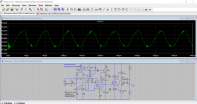
Why do we see this kind of behaviour on so many respected designs ? Is it real or is it just an artefact of the simulation. Even Doug Selfs 'Blameless' does this and this effect happens across a whole range of designs. These images show the base current to the VAS stage.
Any ideas anyone ?
If the quiescent current is reduced the effect becomes very pronounced and yet the main amplifier output remains unaffected by all this. What is the mechanism for this.
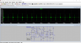
Attachments
"The directionality was PROBABLY caused by differences in the way the two RCA plugs were soldered to the cable; any bumps or discontinuities in the solder or RCA plug will cause a change in the characteristic impedance, which will cause higher-amplitude reflections in one direction than in the other."
What bugs me is the guessing of the cause. They gather data, great, and then guess ( I'm guessing uneducated, does the author have any formal education in EM theory?) at the cause. And even though it's obviously a guess, I think 90% of the readers believe it and will regurgitate as fact. How hard would it have been to reflow the solder and test again. These tests are pseudo science done to sell magazines.
What bugs me is the guessing of the cause. They gather data, great, and then guess ( I'm guessing uneducated, does the author have any formal education in EM theory?) at the cause. And even though it's obviously a guess, I think 90% of the readers believe it and will regurgitate as fact. How hard would it have been to reflow the solder and test again. These tests are pseudo science done to sell magazines.
Mooly if you will start a new thread whose title does not include the word Blowtorch, but does include a description of the problem shown in post #8464,
I promise to reply and point out that your input stage has a transconductance of about 9 millisiemens. Then I will point to the equation in the classic IEEE journal paper, where you plug in transconductance, hit a couple keys on a calculator, and say "wow".
I promise to reply and point out that your input stage has a transconductance of about 9 millisiemens. Then I will point to the equation in the classic IEEE journal paper, where you plug in transconductance, hit a couple keys on a calculator, and say "wow".
Even if the shape/form of the solder joints caused a minor RF impedance discontinuity, how does this affect signal at audio band ?."The directionality was PROBABLY caused by differences in the way the two RCA plugs were soldered to the cable; any bumps or discontinuities in the solder or RCA plug will cause a change in the characteristic impedance, which will cause higher-amplitude reflections in one direction than in the other."
What bugs me is the guessing of the cause. They gather data, great, and then guess ( I'm guessing uneducated, does the author have any formal education in EM theory?) at the cause. And even though it's obviously a guess, I think 90% of the readers believe it and will regurgitate as fact. How hard would it have been to reflow the solder and test again. These tests are pseudo science done to sell magazines.
Dan.
Did you read the article? Nobody claimed there was an audio-band difference, but a measured difference in jitter (whith a bad source).
Just finishing up a small arena in Utica NY. They decided in August they should do something. Put it out for bids ending August 30 th. First game was last night.
My crew did a great job getting all the loudspeakers installed working only at night as they had pretty much fully booked the place for hockey practices during the day for a pro team, the local college and high school practices.
The Danley folks had built the loudspeakers in advance, so there was little waiting time for those.
The down side is even though they have had many sound systems before they never used anyone to turn the knobs! The video control room would just send their audio feed to the system and hope a compressor would keep the level uniform. Ah that just can't work. Setting voltage limits is not the same as setting perceived loudness levels. The other problem is mixing sound on a 3" plastic box loudspeaker doesn't let one know what it will sound like on a system with 100+ woofers.
So the first game managed to go off with a few small issues that the audience didn't notice. The announcer feeds to home and visitor radio broadcasters were set lower than they expected and without a sound system operator no one there knew how to turn up the levels. So the video guys ran some lines and fed their feed to them. They knew where their knobs where!
Another issue was the loudspeaker protection limiters needed to limit the high frequencies to the compression drivers to under 30 volts and those controls were hard to find in the amplifier's digital signal processor.
The issue that was a bit of a problem was none of the users knew what a gain trim control was! They are found in the replay sources, on the wireless microphones and also on the mixing board. Gain trims are used so that you don't have the audio signal clip the electronic's before you get to a volume control. So with the inexperienced announcer who would hold the microphone to his screaming lips a bit of trim was required.
Now for humor just before the game started they gave me the sound system deposit check.
After a week or two my guys will go back to review the training they gave the operators and make the changes they have now figured out they need.
Next step will be to add more coverage to the system in areas they now realize should be covered and perhaps more importantly install volume controls for each locker rooms' loudspeakers. How they didn't have them before stumps me.
BTY sound systems for these kinds of venues run around $100 per seat. When I started it was $20.00.
Mooly if you will start a new thread whose title does not include the word Blowtorch, but does include a description of the problem shown in post #8464,
I promise to reply and point out that your input stage has a transconductance of about 9 millisiemens. Then I will point to the equation in the classic IEEE journal paper, where you plug in transconductance, hit a couple keys on a calculator, and say "wow".
Thanks Mark 🙂 Its not actually my thread but one that I was involved in.
Its all here (the later posts):
My attempts at a design of a 3 stage amplifier
Edit... I see you have found it 🙂
The shape of a solder joint may modify a bump in characteristic impedance which will be noticeable when the joint is bigger than maybe wavelength/50. Let's say it was 5mm in size. This will affect 1.2GHz upwards. Not much effect on digital audio? A much bigger effect will be caused by using RCA connectors. Therefore silly to worry about minor change due to solder bump, with major change due to wrong connector.
Did you read the article? Nobody claimed there was an audio-band difference, but a measured difference in jitter (whith a bad source).
They claimed the difference in jitter with direction was audible as well as measurable. Didn't read the whole article so not sure how they tested audibility, but I doubt it was a rigorous blind testing. And if you believe these magazines listening tests I've got cable lifters for sale.
So, what is this wrongness with RCA connectors causing asymmetry of jitter?... A much bigger effect will be caused by using RCA connectors. Therefore silly to worry about minor change due to solder bump, with major change due to wrong connector.
So, what is this wrongness with RCA connectors causing asymmetry of jitter?
The specified impedance of the SPDIF interface is 75 ohms. An RCA plug's characteristic impedance is ~55 ohms. When swept with a TDR this will show up as a small discontinuity, however...the actual length of the RCA plug/jack is very short, so it's effects will only be seen at frequencies where this is an appreciable % of wavelength. A magnification of the leading/trailing edges of an SPDIF signal being transmitted through an RCA SPDIF cable can show slight irregularities, but in my experience since it is a stable effect, there is no appreciable BER induced by the RCA interface using short, high quality 75 ohm SPDIF cables. If one is using poor quality or long cables, the resulting loss in amplitude could potentially cause the RCA interface issue to be an issue. This is one reason professional equipment often uses 75 ohm BNC connectors, but this often causes problems when intermixed with 50 ohm BNC cabling...and so it goes...
Cheers,
Howie
Hi Howie,
Unfortunately the two versions of BNC will mate and can cause damage.
All,
82R and 75R cable can be used with RCA connectors, and this works fine most times. You'll want to be using a name brand connector, like switchcraft for example.
-Chris
Unfortunately the two versions of BNC will mate and can cause damage.
All,
82R and 75R cable can be used with RCA connectors, and this works fine most times. You'll want to be using a name brand connector, like switchcraft for example.
-Chris
"Real" 75 Ohm BNCs are very rare. I think I have seen 1 in 30 years. Usually you get a 50 Ohm without the plastic and it's close enough up to to 100 MHz .
N connectors are available in true 75 Ohm and 50 Ohm and are not intermateable without potential damage.
RCAs with an air dielectric are still less than 50 Ohms.
In the Stereophile reference the jitter was really bad to start with. Anything using a modern SPDIF receiver would have 1/100 the jitter or less to start with. (Except some audiophile stuff) and would only react to a cable if it was astonishingly bad. I have used 99 cent RCA audio cables and seen no difference in jitter.
None of this relates to analog interconnects.
Demian,
Real 75 ohm BNC connectors have a center pin that is a bit different if I recall correctly. About the only ones I ever use. They are made for analog video use where everything is 75 ohms. They also cost a bit more. Of course the require a bit different crimper.
The feed throughs and patch bays are also made in 75 ohm. It does show up when you test with a TDR if the connector is wrong.
Pretty sure by now I have used tens of thousands of them. I did once have a supplier provide the wrong ones. Things really hit the fan. The manufacturer sent out someone to check them out and found the supplied product was counterfeit.
The only 50 ohm ones I use are for antenna cables and these are purchased in small quantities from a different manufacturer and stored separately. Biggest problem is explaining to folks is that to get less loss in coax than from adding another 50 feet to the stadium path length requires thicker coax and special connectors that reduce the diameter down to fit.
Last edited:
There have been lots of debates on lots of forums on whether 50R and 75R BNC have the same size pin or not and so whether they can damage each other or not. The consensus as far as I could tell is that they are supposed to have the same pin size but sometimes may not, and it is the presence or absence of the dielectric which determines the impedance i.e. a 50R without the plastic is a real 75R, there is no 'more real' version.
I would expect an RCA to be down around the 30R region. Any pigtails used to connect to it would boost the impedance by adding inductance, so might actually help!
I would expect an RCA to be down around the 30R region. Any pigtails used to connect to it would boost the impedance by adding inductance, so might actually help!
- Status
- Not open for further replies.
- Home
- Member Areas
- The Lounge
- John Curl's Blowtorch preamplifier part III